IEC60747-9
This chapter first describes the important parts of the IEC 60747-9 standard with regards to switching times and energies. Afterwards it gives some notes and explains how PD1000A software adapts this standard or deviates from it. The standard is applicable for discrete (according to title) IGBTs.
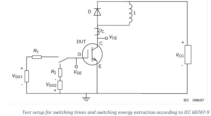
Test setup
The test setup for both switching times and energies is a standard clamped inductive load double pulse test.
Measurement Procedure and Waveform
Measurement Procedure
The gate voltage level VGG1 and VGG2 and the supply voltage VCC are set to the specified values. The minimum turn-on pulse duration must ensure a complete saturation of the IGBT. The collector current IC, the gate emitter voltage VGE and the collector emitter voltage VCE are monitored simultaneously.
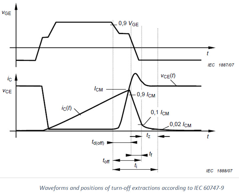
EOFF is the integral of VCE x IC x dt. Integral time TI starts from the 90 % fall point of VGE and ends at the specified low IC point, the 2 % point of IC before turn-off. The turn-off power dissipation is the product of the switching frequency and the turn-off energy per pulse as determined by the integration.
Specified Conditions
- Case or ambient or virtual junction temperature of the IGBT and the diode
- Voltage of intermediate circuit VCC
- Collector current IC just before 1st turn-off (ICM)
- Gate voltage -VGE before and +VGE after turn-on
- Gate resistor R1 (RGON)
- Characteristics of freewheeling diode
Voltage and Current Levels:
- Some levels are not defined properly in the standard
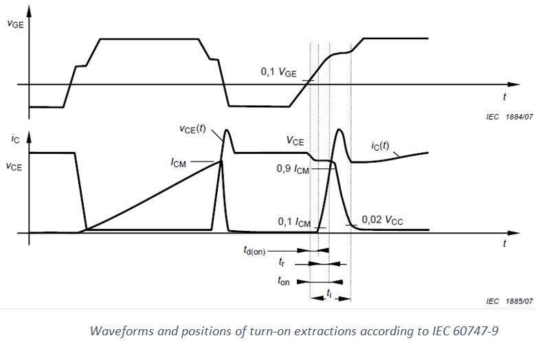
- 0.9 VGE and 0.1 VGE is with reference to 0 V, not the negative gate voltage.
- Example: gate voltages of 20 V/-5 V would lead to 10 %=2 V and 10 %=18 V
- 0.9 ICM, 0.1 ICM and 0.02 ICM are with reference to 0 A.
- 0.02 VCC should be 0.02 of supply voltage according to standard. We measure VCE between pulses and use this as 100 % reference. 0 % reference is measured at the end of the first pulse while device is still fully turned on. This way 2 % is mostly able to be reached. Without this it is often not possible for high currents due to beginning of saturation etc.
- Example: Test is measured at VCC = 800 V. At the end of first pulse we measure VCE = 10 V, between pulses we measure VCE = 795 V. This is 0 % and 100 %. Because of this 0.02 VCC is 25.7 V instead of 16 V or 15.9 V.
- The levels are measured on the original signals, except for 100 % of ICE. To extract 100 %, the I_CE signal is low pass filtered with a frequency of 10 MHz.
Start and end times
- Currently software always searches first crossing of voltage/current levels searching from left to right. This can lead to smaller times or energies when there is a lot of ringing in the system etc.. Infineon suggested searching from the right for searching for e. g. the end of ti
- The following formulas are used as start and end times of turn on/off:
- start time = turn on/off time
- end time = start + delay + rise/fall time


