Inserting Calibration Standards
This topic details how to insert the calibration standards into the test fixtures.
- Inserting Cal Standards into the PD1000A TO-220 and TO-247 Test Fixtures
- Inserting Cal Standards into the PD1000A SMD Test Fixture
Inserting Cal Standards into the PD1000A TO-220 and TO-247 Test Fixtures
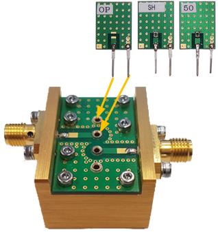
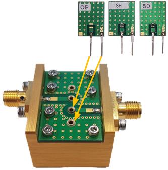
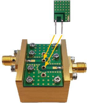
Inserting calibration standards into the test fixtures is the same as inserting your device to be tested. This section shows the orientation of the calibration standards inserted into the test fixture.
Important: Notice the orientation of each standard.
Input Standards
Two pins on each OPEN, SHORT, and 50 W LOAD calibration standards. The Input calibration standards connect between the Gate and Source/Emitter.
Output Standards
Two pins on each OPEN, SHORT, and 50 W LOAD calibration standards. These are the same standards used on the Input. The calibration standards connect between the Drain/Collector and Source/Emitter.
THROUGH Standard
Two pins on the THROUGH Standard. There is no label on this standard It connects between the Gate and the Drain/Collector.
Inserting the Cal Standards into the PD1000A SMD Test Fixture
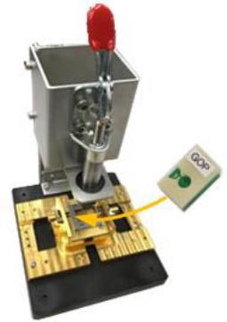
Use the Test Fixture PC Board, Vertically Conductive Sheet, and Frame Guide supplied with the Surface Mount Device (SMD) Test Fixture for fixture calibration.
Inserting calibration standards into the test fixture is the same as inserting your device to be tested. This section shows the orientation of the calibration standards inserted into the test fixture.


