Understanding the Add PXI Chassis Window
The Left Pane
The left pane of the Add PXI Chassis window provides the form you will fill in to add a PXI chassis to your configuration. See Using the Add PXI Chassis Utility.
The list of chassis vendors shows all vendors whose chassis are represented in the list of models.
The list of chassis models is derived from the available set of chassis description files, so it typically shows all the chassis you have installed.
The Chassis Description File field shows the description file that corresponds to the selected vendor and model.
The PCI bus-to-segment mappings shown below the chassis description file represent the segments in the selected chassis model.Therefore, the number of represented mappings varies depending on the model selected.
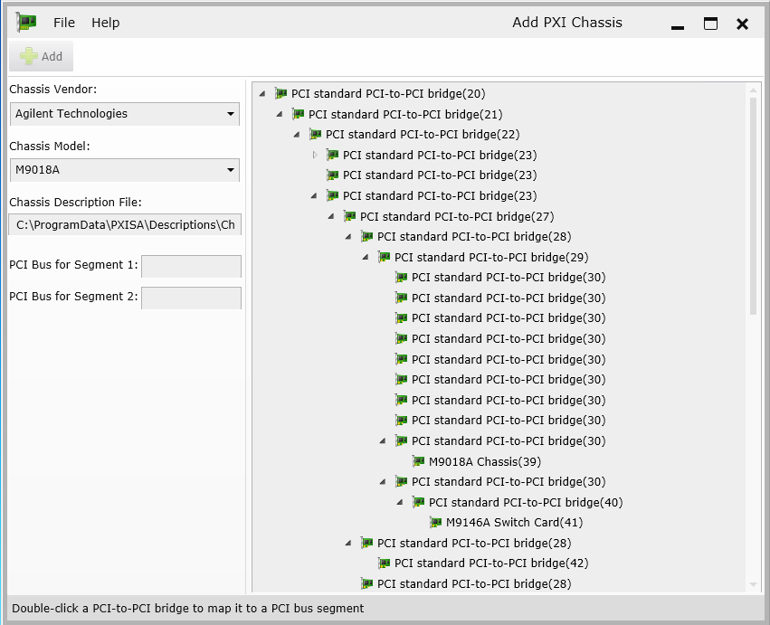
The Right Pane
The right pane shows this PC's PCI tree. You can expand or collapse sections of the tree by clicking the arrows . Since this is the PC's entire PCI hierarchy, you'll see equipment other than PCI-to-PCI bridges: for example, when collapsed, the tree for this example looks like this:
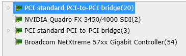
However, for the purposes of using the Add PXI Chassis utility, we are only interested in the PCI-to-PCI bridges and the equipment connected to them (such as the M9018 chassis and the M9146A switch card shown above).
The number in parentheses following the description of each bridge or other equipment is the PCI bus number corresponding to this equipment. For example, in the image above, the PCI standard PCI-to-PCI bridge shown at the top of the tree is on bus number 20.