The Battery Cycle Operation
The Battery Cycle Window
Battery Cycle Configuration
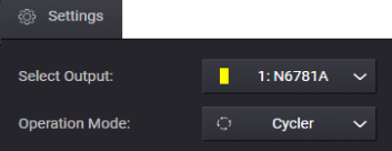
Select the Battery Cycle operation from the Settings menu or Icon.
![]()
or
The Battery Cycle Window
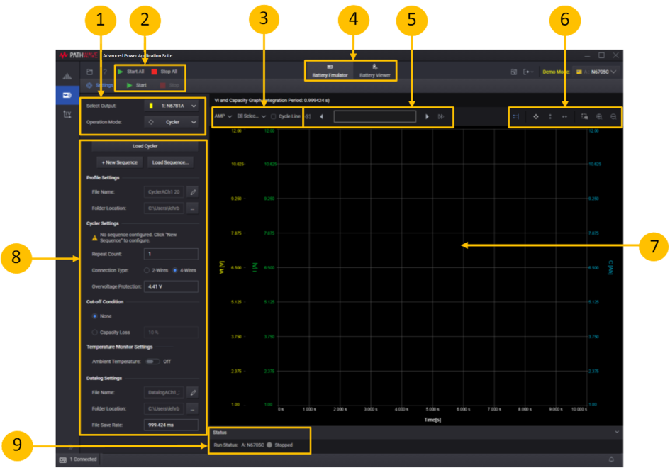
1. Settings area - lets you select the Cycle operation.
2. Start or Start All - click Start or Start All to start the cycle operation on either the specified instrument output or all outputs.
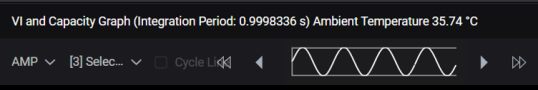
3. Graph settings - lets you specify additional graph settings (Ampere or Charge-rate; Current, Voltage, or Capacity). Checking Cycle Line adds cycle separation lines to the graph.
4. Display selection - lets you display either the Battery Emulator or the Battery Viewer.
5. Data Preview Bar - indicates the portion of the data that is visible on the graph.
6. Graph toolbars - lets you autoscale and zoom in or out of the display area.
7. VI and Capacity graph - displays battery VI and capacity measurements as the cycle operation is run.
8. Settings - specify the settings for the new sequence, or adjust the settings of the existing sequence.
9. Run Status - displays the run status of the selected instrument outputs.
Battery Cycle Configuration
The following steps describe the battery cycle operation.
Step 1. In the Settings area on the left side of the window, specify the battery cycle settings:
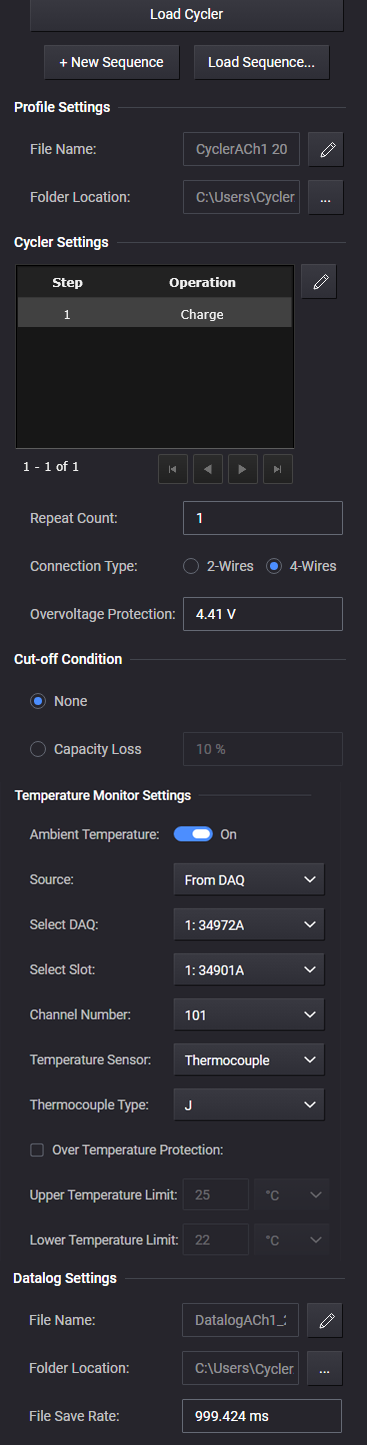
Load Cycler - lets you re-load a stopped cycler operation and continue at the cycle where it was stopped.
+ New Sequence - lets you create a new battery cycle sequence using the Edit Battery Cycle Sequence dialog.
Load Sequence - lets you load a previously created sequence. Battery cycle sequences are identified by a .json file extension.
Profile Settings - lets you select a profile filename and location. A Cycler profile will be generated automatically every time a cycler test is started. If the cycler test is stopped by the user or other factors like a timeout, you can resume the cycler profile by restarting the loaded profile.
File Name - shows the loaded profile name. You can specify an existing filename or specify a new profile.
Folder Location - select the folder location of the generated profile.
Cycler Settings - lets you adjust specific settings in the cycle sequence. The cycle preview area lists all of the steps in the presently loaded (or active) sequence.
Step column – identifies the steps by number displays the name of the open profile.
Operation column - identifies the step function: charge, discharge, or rest.
Pencil icon - select  to open the Edit Battery Cycle Sequence dialog that lets you edit the highlighted step.
Navigation controls - use the  controls to scroll through the sequence steps.
Repeat Count - specify the number of times the battery cycle sequence repeats. The minimum repeat count is 1; the maximum repeat count is 1000.
Connection Type - specify the measurement connection type of the connected instrument (2- or 4-wire sensing).
OverVoltage Protection - specify the overvoltage limit. The default overvoltage value is set to the Upper Threshold Vt setting +5%. However you have the option to change the overvoltage to a higher value. A status message will indicate that the overvoltage protection has been adjusted by the user.
Cut-off Condition
None – when selected, the cycler operation stops when all cycles have completed.
Capacity loss – when the capacity loss has met the specified percent, the cycler operation will complete the present cycle and stop. The capacity loss is calculated based on the number of steps in the cycle. You can specify capacity loss in either percent (0 to 100) or milli-percent.
Temperature Monitor Settings - lets you include the ambient temperature settings during the Battery Cycler operation. Only applies to instruments that have an external temperature monitor. The ambient temperature will be displayed along the top of the VI and Capacity Graph along with the Integration Period.
The following selections are only available if Ambient Temperature has been selected, and if there is DAQ connected to the application.
Ambient Temperature File Name - Slide the switch to enable this feature.
Source – select the source of the external temperature monitor.
Select DAQ - select any connected DAQ instrument to perform temperature measurements.
Select Slot - select any available DAQ slot where a temperature sensor is connected to measure ambient temperature.
Channel Number - select any DAQ Channel Number that has a temperature sensor connected to measure ambient temperature. You cannot select the DAQ channel number as an Output channel.
Temperature Sensor - select either Thermocouple or Thermistor temperature sensor.
Thermocouple Type - specify the thermocouple type from the dropdown list.
Over Temperature Protection – when selected, temperature protection stops the battery cycle operation when an temperature limit is detected.
Upper Temperature Limit – Specifies the upper temperature limit.
Lower Temperature Limit – Specifies the lower temperature limit.
Data Log Settings
A data log of the voltage and current measurements of the existing operation is automatically generated when the operation is started.
File Name - when selected, specify the filename of the data log.
Folder Location - select the folder location of the data log.
File Save Rate - specify the rate at which data is saved to a file. If the rate is 1 s, measurement data is saved once every second. The file save rate must be divisible by the instrument's integration period.
Step 2. When you select Start, the battery cycle sequence will be displayed in the VI and Capacity Graph.