The Emulation Operation
The Emulation Window
Battery Emulation Operation
Battery Emulation Example
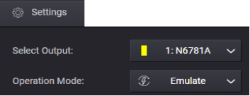
Select the Emulation operation from the Settings menu or Icon.
![]()
or
The Emulation Window
The link below shows the main window of the Emulation operation.
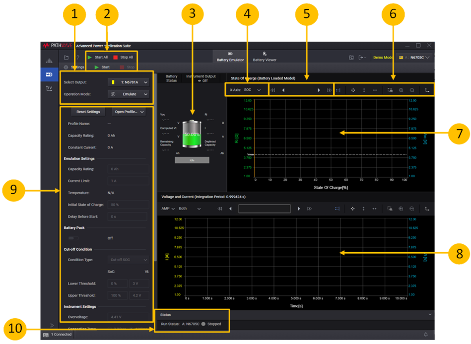
1. Settings area - lets you select the Battery Emulation operation.
2. Start or Start All - click Start or Start All to start and display the profile of either the specified instrument output or all outputs.
3. Battery status - displays a "snapshot" of the battery parameters when the profile is run.
4. Graph settings - lets you specify additional graph settings (Ampere or Charge-rate; Current, Voltage, or Capacity).
5. Data Preview Bar - indicates the portion of the data that is visible on the graph (all of the data in this example).
6. Graph toolbars - lets you autoscale and zoom in or out of the display area.
7. Voltage and Current - charts the battery voltage and current of the profile operation. You can configure the Current axis to display either Amps or Charge rate.
8. State of Charge - charts the state of charge of the profile operation. You can configure the horizontal axis to display either state of charge in percent, or Capacity in Amp-hours.
9. Settings - specify the settings for the new profile, or adjust the settings of the existing profile.
10. Run Status - displays the run status of the selected instrument outputs.
Battery Emulation Operation
The following steps describe the battery emulation operation.
Step 1. In the Settings area on the left side of the window, specify the Emulation settings:
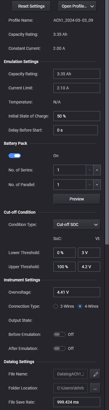
Reset Settings - Resets the Battery Emulation settings to the default settings.
Open Profile - Opens an existing discharge or charge profile. Select the directory where the profile is located. You can opt to open a profile that includes ambient temperature information, or an previous version profile that does no include temperature information
Profile Name – displays the name of the open profile. The drop-down menu lets you choose a profile:
Without Temperature - which lets you open one profile without an associated ambient temperature.
With Temperature - which lets you select up to ten profiles with associated ambient temperature values. A list displays every profile name and ambient temperature value. Note that every profile listed must be using the same temperature unit (either Celsius or Fahrenheit).
Capacity Rating - displays the capacity rating of the profile in amp-hours.
Constant Current - displays the constant current charge of the profile in amps.
Emulation Settings - lets you adjust specific settings in the Emulation profile:
Emulate Mode - this selection is only available for Keysight E36731A. The drop-down menu lets you choose an emulation mode:
Auto - automatically switches between Charging and Discharging mode. For lower current noise performance, select Charging or Discharging mode.
Charging - emulates battery charging.
Discharging - emulates battery discharging.
Capacity Rating - specify the capacity of the profile in amp-hours.
Current Limit – specify the current limit in amps.
Select Profile – this setting will only appear when there is more than one profile available with overlapping temperature ranges (as shown under "Show me the emulation settings" above). This field lets you enter the temperature range of the profile that you want to emulate.
Temperature - displays the ambient temperature associated with the opened profile. You can only enter a temperature value that is within the associated temperature range. Changing the temperature to a different value will update the State of Charge in the battery profile model with corresponding temperature value. N/A indicates that the opened profile does not contain ambient temperature.
Initial State of Charge - specify the initial state of charge in percent.
Delay Before Start - specify the delay before starting the profile in seconds.
Slow Down Factor - this selection is only available for Keysight E36731A. Four slow down factors can be specified: 1, 10, 50 and 100. A higher slow down factor can be specified when running emulation with higher capacitance loads. This helps improve current and voltage noise when running the emulation operation.
Note that the allowable voltage and current settings depend on the operating ranges of the instrument. For example, for the N6781A power module - if you program a voltage threshold of 18 V, you cannot program a current value greater than 1 A. To program a current of 3 A, the voltage threshold settings must be in the 6 V range.
Battery Pack - turn the toggle switch ON to configure the cells in the battery pack.
Refer to Emulating a Battery Pack for further information.
Cut-off Condition
Condition type - select from Cut-off SOC (state of charge), or Cut-off Voltage.
Lower Threshold - specify a lower threshold that serves as cut-off for the discharge operation. You can specify a state-of-charge in percent, along with the voltage measured at the battery terminals. Alternatively, you can select the Cut-off Voltage only.
Upper Threshold - specify an upper threshold that serves as cut-off for the charging operation. You can specify a state-of-charge in percent, along with the voltage measured at the battery terminals. Alternatively, you can select the Cut-off Voltage only.
Instrument Settings
Overvoltage - specify the emulation overvoltage limit. The default overvoltage value is set to the Upper Threshold Vt setting +5%. However you have the option to change the overvoltage to a higher value. A status message will indicate that the overvoltage protection has been adjusted by the user.
Connection Type - specify the measurement connection type of the connected instrument (2- or 4-wire sensing.
Output State - lets you specify the output state before and after the emulation:
Before Emulation [On] - turns the output on (or off) immediately before the emulation starts. Before turning the output on, a pop-up prompt message will inform you of the voltage and current values that will be applied if you answer "YES".
After Emulation [On] - keeps the output on after the emulation has completed. If you set the instrument output off after the emulation finishes, there will be a notification at the right bottom of the main window: Instrument Output state is off.
Data Log Settings
A data log of the voltage and current measurements of the existing operation is automatically generated when the operation is started.
File Name - specify the filename of the data log.
Folder Location - select the folder location of the data log.
File Save Rate - specify the rate at which data is saved to a file. If the rate is 1 s, measurement data is saved once every second. The file save rate must be divisible by the instrument's integration period.
Step 2. When you select Start, the emulation waveform will be displayed in the Discharge Window.
Battery Emulation Example
The following examples describes the information that appears on the display when a discharge or charge emulation is run. Refer to Starting and Stopping for more information.
Note that the BenchVue Advanced Battery Test and Emulation application supports bi-directional emulation. This is because in normal use cases batteries are discharged and charged repeatedly. The discharge or charge operation is determined by the current direction. Current is either flowing into or out of the battery. The discharge\charge emulation will switch within the specified Upper and Lower Threshold boundaries.
The following example illustrates the emulation discharge display.
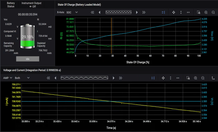
Battery Status - The Battery status area displays the running state of the discharge or charge emulation. Voc is the open-circuit voltage of the emulation during the discharge operation. Computed Vt is calculated based on (current array fetched from instrument * internal resistance). Ri is the internal resistance of the emulation during the specified operation. I indicates the current that is being discharged or charged throughout the specified operation. Consumed Capacity is the energy in Amp hours that has been consumed by the load as the emulation is discharging. Charged Capacity is the energy in Amp hours that has been generated by the charge emulation. Remaining Capacity is the capacity in Amp hours still remaining in the emulation as it is discharging or charging.
The red line on the graph indicates the specified cut-off voltage.
State of Charge - This graph does not updated during runtime. It only displays the Ri and Voc values from the loaded profile.
Voltage and Current - The Voltage and Current graph displays the voltage and current that is either being consumed by the load connected to the battery, or charged back into the battery during the emulation operation. The voltage and current data are displayed on the graph at the specified integration period.
In addition to amperes, you can also check "C-Rate", which plots the current data in Coulombs.
A red line indicates the specified cut-off voltage.