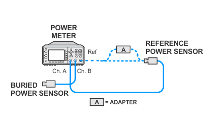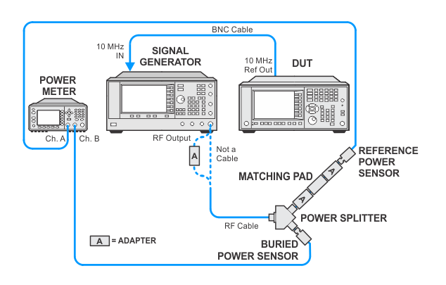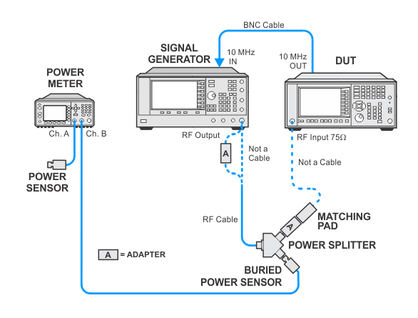
In the following setups, cables are designated as solid lines and direct connections are designated as dashed lines.
CXA — N9000A/B with Option C75
This test measures the amplitude error of the analyzer’s 75 ohm input from the reference amplitude at 50 MHz, as a function of frequency.
A “buried power sensor” technique is used to characterize the 5.7 dB loss due to the external minimum loss pad and the tracking error of a power splitter in order to avoid the relatively large specified tracking error. This technique reduces the measurement uncertainty to verify the frequency response specification for the 1 MHz to 1.5 GHz range. The buried sensor calibration is valid for four hours.
The related adjustment for this functional test is Frequency Response (Option C75).
Click here for troubleshooting.
|
Test Equipment |
Model Number |
|---|---|
|
RF Signal Generator |
PSG Models |
|
Power Meter |
N1914B |
|
RF Power Sensor |
N8482A |
|
75 W Power Sensor |
8483A |
|
RF Power Splitter |
11667A |
|
Minimum Loss Pad (50 W to 75 W) |
11852B Option 401 |
|
Type-N Cable |
11500C |
|
BNC Cable |
8120-1840 |
|
Type-N (m) to Type-N (m) adapter |
1250-1475 |
|
Type-N (m) (50 W) to Type-N (f) (75 W) adapter |
1250-0597 |
|
Type-N (f) (75 W) to Type-N (f) (75 W) adapter |
Huber + Suhner 31_N-75-0-2 /133_NE (Item no. 22542612) |
|
3.5 mm (f) to Type-N (f) adapte |
1250-1745 |
|
2.4 mm (f) to Type-N (f) adapte |
11903B |
|
|
In the following setups, cables are designated as solid lines and direct connections are designated as dashed lines. |


