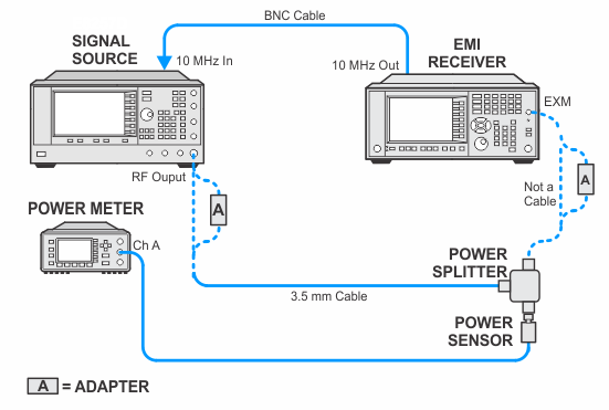
N9048B PXE with Option EXM
This adjustment inputs a calibrated –25 dBm signal into the External IF INPUT port. Then the Amplitude Error is measured at the center frequency and at offset frequencies across the IF Bandwidth. The offset frequencies are nominally spaced in 4 MHz intervals. If Option B40, B85, or B1X is installed, the adjustment is repeated for those paths.
Click here for troubleshooting.
|
Test Equipment |
Model Number1 |
|---|---|
|
Microwave Signal Generator #1 |
PSG Models |
|
Power Meter |
N1914A |
|
Microwave Power Sensor |
N8485A |
|
Microwave Power Splitter |
11667B |
|
Cable, BNC |
8120-1840 |
|
Cable, coaxial 3.5 mm |
11500E |
|
Adapter, 3.5 mm (m) to 3.5 mm (m) |
83059A |
|
Adapter, 3.5 mm (f) to 3.5 mm (f)
|
83059B |
|
Adapter, 2.4 mm (f) to 3.5 mm (f)
|
11901B |
|
Adapter, 3.5 mm (f) to Type-N (m)
|
08485-60005 |
|