This adjustment applies to models with Option CR3.
|
|
This adjustment applies to models with Option CR3. |
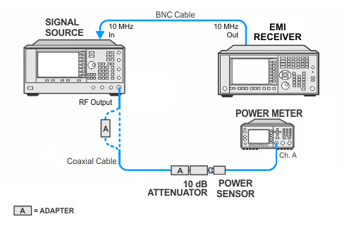
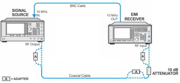
A 300 MHz, -10 dBm signal is applied to the analyzer and an internal alignment is called. The alignment adjusts the IF attenuator for Burst Carrier and IF Output operations.
There is no associated verification test for this adjustment, but the IF Output Gain Utility can be used to verify it.
|
Test Equipment |
Model Number1 |
|---|---|
|
Microwave Signal Generator |
PSG Models |
|
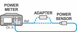
Power Meter |
N1914A |
|
Power Sensor |
N8482A CFT |
|
Fixed Attenuator, 10 dB |
8491A Option 010 |
|
Cable, coaxial 3.5 mm |
11500E |
|
Cable, BNC |
8120-1840 |
|
Adapter, Type-N (f) to 3.5 mm (f) |
1250-1745 |
|
Adapter, Type-N (m) to Type-N (m) |
1250-1475 |
|
Adapter, Type-N (m) to 3.5 mm (f)
|
1250-1744 |
|
Adapter, Type-N (m) to 2.4 mm (f)
|
11903D |
|
Adapter, 3.5 mm (f) to 3.5 mm (f)
|
83059B |
|
Adapter, 2.4 mm (f) to 3.5 mm (f)
|
11901B |
|