Absolute Amplitude Accuracy at 50 MHz Performance Test
This test measures the absolute amplitude of the EMI receiver at 50 MHz.
A synthesized signal source and two precision attenuators are used as
the signal source to the DUT. A power meter is used to measure a
reference power level from the signal source. The precision attenuators
are switched to provide a series of signal power levels below the reference
power.
The combined attenuation of the 10 dB and 1 dB precision attenuators
is never set below 5 dB in order to maintain a good match between the
signal source and the DUT. In addition, a 10 dB fixed
attenuator is placed between the DUT and the precision step attenuators
to further improve the match. Also, a 6 dB fixed attenuator is
placed between the source and the step attenuator to control match.
Varying the signal level at the DUT input causes various ADC ranges
to be enabled. The resolution bandwidth and frequency span on the DUT
are varied, resulting in different pre-filter path and bandwidth switching
errors. These errors are all absorbed by the DUT in giving its indicated
reading of the exact absolute power levels presented by the signal generator/attenuator
chain. The test is performed on both the RF Input 1 and RF Input 2.
|

|
This test requires step attenuator calibration data to obtain valid results.
Make sure you enter the calibration data for the step attenuators that
you're using. Please refer to the Enter Equipment Calibration Data section
in the TME help for details on how to enter this data. You must enter
the data for the following columns to obtain valid results: Attn(dB),
Uncert(dB), and ReflSize.
|
Click here for troubleshooting.
Required Test Equipment
|
Test Equipment
|
Model Number1
|
|
Microwave Signal Generator #1
|
PSG Models
(see equipment list)
|
|
Power Meter
|
N1914A
|
|
RF Power Sensor
|
N8482A CFT
|
|
Attenuator, 10 dB Fixed
|
8491A Option 010, H33
|
|
Attenuator, 6 dB Fixed
|
8491A Option 006, H33
|
|
Attenuator, 10 dB Step
|
8496G Option 001, H50
|
|
Attenuator, 1 dB Step
|
8494G Option 001, H50
|
|
Attenuator Driver
|
11713B
|
|
Attenuator Interconnect Kit
|
11716A
|
|
Cable, Type-N
|
11500C
|
|
Cable, BNC
|
8120-1840
|
|
Viking Cable (attenuator control)
|
8120-2703
|
|
Adapter, 3.5 mm (f) to Type-N (f)
|
1250-1745
|
|
Adapter, 2.4 mm (f) to Type-N (f)
- For 2.4 mm source
- For Option 544
|
11903B
|
|
Adapter, Type-N (f) to Type-N (f)
|
1250-1472
|
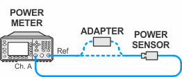
Connection Setups
Power Meter Calibration
Measure Source Setup
Absolute Amplitude Accuracy Test Setup (RF Input 1)
Absolute Amplitude Accuracy Test Setup (RF Input 2)