N9048B PXE
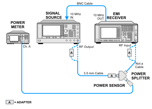
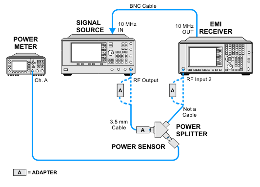
This test measures the Sine Wave Accuracy in time domain scan. In this test a 30 MHz to 18 GHz signal is applied to both the EMI receiver and a power meter. To capture the worst case performance, the span of the DUT must be wide. The signal amplitude is measured at test frequencies at different sections of the span. For each span, the on-bin point is expected to be the most accurate point, and the chunk edge point is expected to be the worst case point.
For each test frequency, the Sine Wave Accuracy is the difference between the amplitude measured by the power meter and the DUT.
Click here for troubleshooting.
|
Test Equipment |
Model Number1 |
|---|---|
|
Signal Source |
PSG Models |
|
Power Meter |
N1914A |
|
Power Sensor |
E9304A Option H18 |
|
Power Splitter |
11667A |
|
Cable, BNC |
8120-1840 |
|
Cable, 3.5 mm coaxial |
11500E |
|
Adapter, 3.5 mm (f) to 3.5 mm (f)
|
83059B |
|
Adapter, 2.4 mm (f) to 3.5 mm (f)
|
11901B |
|
Adapter, Type-N (m) to 3.5 mm (f)
|
1250-1744 |
|
Adapter, Type-N (m) to 2.4 mm (f)
|
11903D |
|
Adapter, Type-N (m) to Type-N (m) |
1250-1475 |
|