This test measures the Conducted Band return loss in both 10 dB attenuation and 0 dB attenuation. CISPR 16-1-1:2019 (Section 4.2) requires that the VSWR below 1 GHz be < 2.0:1 for 0 dB Input Attenuation, and < 1.20:1 for 10 dB Input Attenuation.
The VSWR measurement is broken into two tests: VSWR Conducted Band and VSWR Radiated Band. VSWR Radiated band covers the 30 MHz to 40 GHz range. VSWR Conducted band measurement covers 9 kHz to 30 MHz.
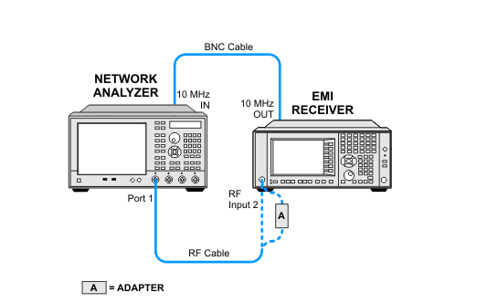
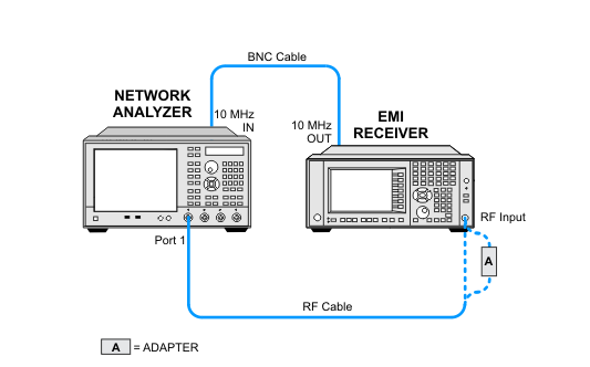
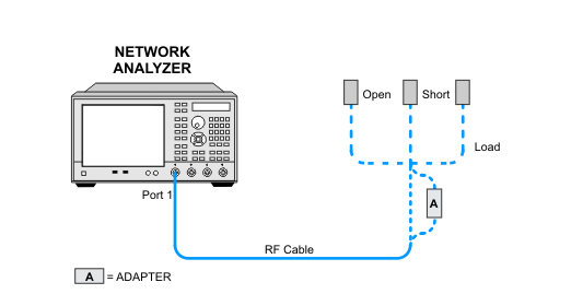
In this test, an ENA-C network analyzer is used to measure the return loss. The Standard EMI Receiver will have a Type-N female connector on both RF inputs.
Option C35 will have a 3.5 mm (m) connector in the RF Input 1 port only. Option C35 will require a Type-N, S11 calibration to be made for RF Input 2, and then a 3.5 mm, S11 calibration to be made for RF Input 1.
Option 544 will have a 2.4 mm (m) connector in the RF Input 1 port only. Option 544 will require a Type-N, S11 calibration to be made for RF Input 2, and then a 2.4 mm, S11 calibration to be made for RF Input 1.
Click here for troubleshooting.
|
Test Equipment |
Model Number1 |
|---|---|
|
Network Analyzer 2 |
E5071C Option 2402 |
|
Mechanical Calibration Kit, 3.5 mm (m)
|
85033E |
|
Mechanical Calibration Kit, 2.4 mm (m)
|
85056A |
|
Mechanical Calibration Kit, Type-N (f) |
85032F |
|
Cable, Type-N |
11500C |
|
Cable, BNC |
8120-1840 |
|
Adapter, Type-N (f) to 3.5 mm (f)
|
1250-1745 |
|
Adapter, Type-N (f) to 2.4 mm (f)
|
11903B |
|