N9038A/B MXE
Gain Compression describes the ability of an EMI receiver to measure relatively low-level signals in the presence of high-level signals.
Gain Compression is measured by applying two signals: one high amplitude signal, and a low amplitude signal. The high amplitude signal is set to yield the specified total power at the input mixer. The low amplitude signal power is chosen to be low enough to not add significantly to the total power at the input mixer. The actual amplitude of the low power signal is unimportant because this is a relative amplitude measurement. What is important is the total mixer power.
A Directional Bridge is used to combine the two signals in Band 0. The Directional Coupler is used as a signal combiner above Band 0. The bridge or coupler provides good isolation between sources, and low thru-loss for the high power source. It is critical that the high power source be connected to the thru arm of the bridge or coupler so the source won’t be driven into an unleveled state. The EMI receiver input attenuator must be set to 0 dB in order to meet the high mixer levels required for the measurement. The high power source will need to output approximately +12 dBm in order to get +3 dBm at the DUT mixer. This amplitude is very close to the Max Leveled power specification of the PSG. Increasing the DUT input attenuation will raise the source levels by an equal amount.
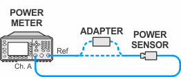
A power meter is used to establish the total mixer power. The low-amplitude signal is measured with the high amplitude signal off. This amplitude is the uncompressed amplitude. The high-amplitude signal is then turned on and the amplitude of the lower-amplitude signal is again measured. This is the compressed amplitude. The difference between the uncompressed and compressed amplitudes is defined as the gain compression.
Click here for troubleshooting.
|
Test Equipment |
Model Number1 |
|---|---|
|
Microwave Signal Generator #1 and |
PSG Models |
|
Power Meter |
N1914A |
|
Microwave Power Sensor |
N8485A CFT |
|
Millimeter Power Sensor
|
N8487A CFT |
|
Microwave Power Splitter |
11667B |
|
Millimeter Power Splitter
|
11667C |
|
Directional Bridge |
86205A |
|
Directional Coupler
|
87300B |
|
Millimeter Directional Coupler
|
87301C |
|
Cable, BNC
|
8120-1840 |
|
Cable, coaxial, 3.5 mm
|
11500E |
|
Cable, coaxial, 2.4 mm
|
8120-6164 |
|
Adapter, 3.5 mm (f) to 3.5 mm (f)
|
83059B |
|
Adapter, 2.4 mm (f) to 3.5 mm (f)
|
11901B |
|
Adapter, Type-N (m) to 3.5 mm (f)
|
1250-1744 |
|
Adapter, Type-N (m) to 3.5 mm (m) |
1250-1743 |
|
Adapter, 3.5 mm (m) to 3.5 mm (m) |
83059A |
|
Adapter, 3.5 mm (m) to 2.4 mm (f)
|
11901D |
|
Adapter, Type-N (m) to 3.5 mm (f)
|
08485-60005 |
|
Adapter, Type-N (m) to 2.4 mm (f)
|
08487-60001 |
|