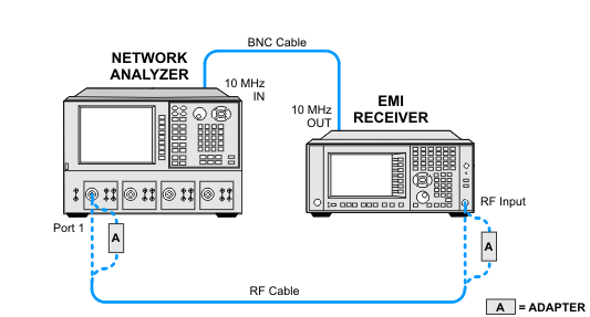
This test measures the Radiated Band return loss in both 10 dB attenuation and 0 dB attenuation. CISPR 16-1-1:2019 (Section 4.2) requires that the VSWR below 1 GHz be < 2.0:1 for 0 dB Input Attenuation, and < 1.20:1 for 10 dB Input Attenuation.
The VSWR measurement is broken into two tests; VSWR Conducted Band, and VSWR Radiated Band. The VSWR Conducted band measurement covers 9 kHz to 30 MHz. The VSWR Radiated band measurement covers the 30 MHz to 40 GHz range. For frequency 18 GHz and below, the specifications refer to CISPR 16-1-1:2019, Section 4.2.
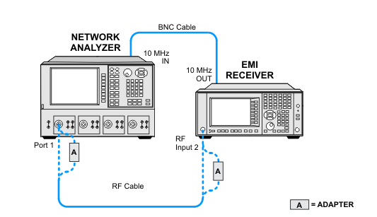
The Standard EMI Receiver will have a Type-N female connector on both RF inputs.
Option C35 will have a 3.5 mm (m) connector in the RF Input 1 port only. Option C35 will require a Type-N, S11 calibration to be made for RF Input 2, and then a 3.5 mm, S11 calibration to be made for RF Input 1.
Option 544 will have a 2.4 mm (m) connector in the RF Input 1 port only. Option 544 will require a Type-N, S11 calibration to be made for RF Input 2, and then a 2.4 mm, S11 calibration to be made for RF Input 1.
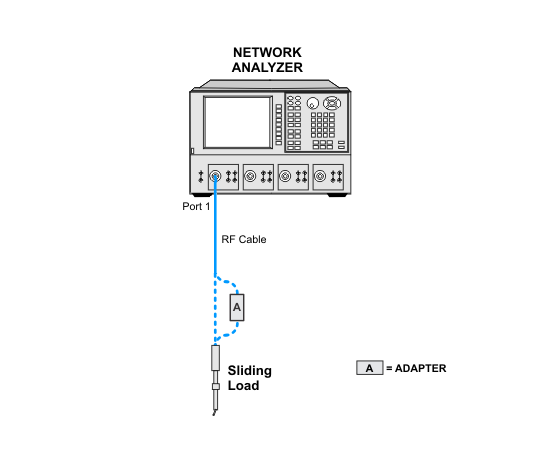
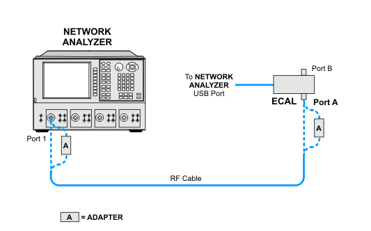
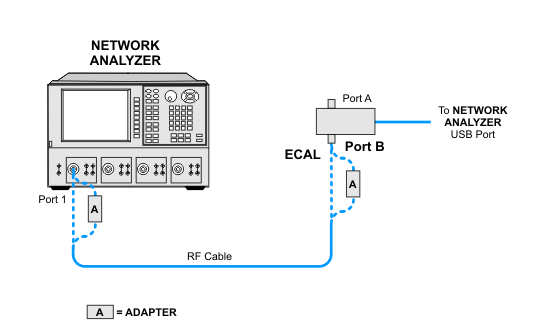
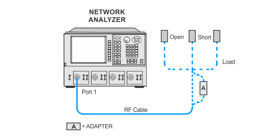
Either a mechanical calibration kit or ECal module can be used for this test. The mechanical kit is the preferred solution.
Click here for troubleshooting.
|
Test Equipment |
Model Number1 |
|---|---|
|
Network Analyzer 1 |
N5247B |
|
Mechanical Calibration Kit, Type-N |
85054B |
|
Mechanical Calibration Kit, 3.5 mm
|
85052B |
|
Mechanical Calibration Kit, 2.4 mm (m)
|
85056A |
|
E-Cal Module,2 Type-N |
N4690D-M0F |
|
E-Cal Module,2 3.5 mm
|
N4691D-M0F |
|
E-Cal Module,2 2.4 mm
|
N4693D-M0F |
|
Cable, BNC |
8120-1840 |
|
Cable, 3.5 mm (f) to PSC-3.5 mm (f)
|
85131E |
|
Cable, 2.4 mm (f) to PSC-2.4 mm (f)
|
85133E |
|
Adapter, Type-N (m) to 3.5 mm (m) |
1250-1743 |
|
Adapter, Type-N (m) to 2.4 mm (m)
|
11903A |
|