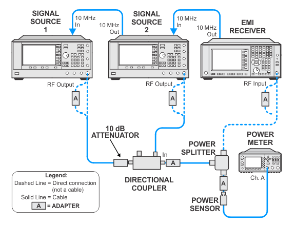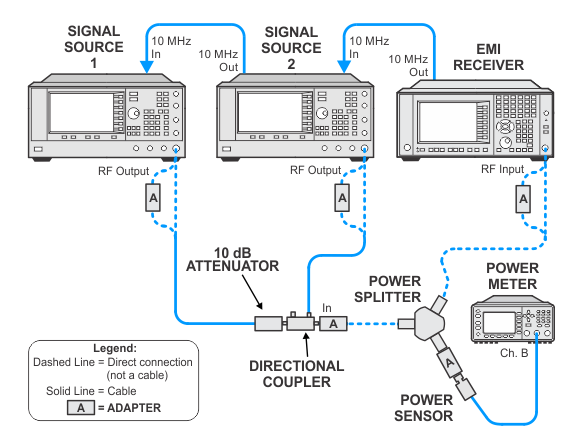
This test measures the Third-Order Intermodulation Distortion produced by two discrete signals, and computes the Third Order Intercept (TOI) point.
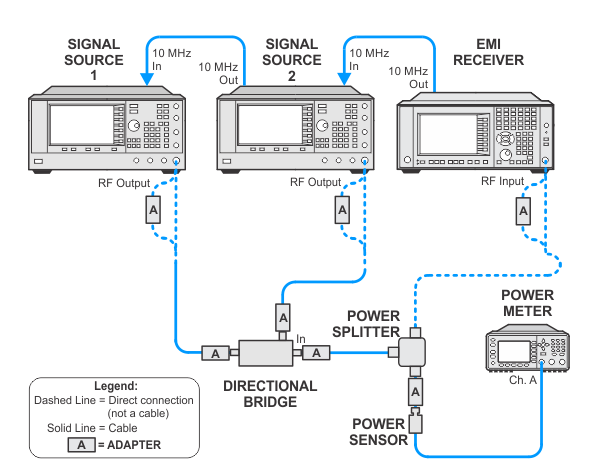
Two signals separated by 100 kHz are combined in a directional bridge or directional coupler (for isolation) and are injected into the EMI receiver input. The EMI receiver measures the amplitude of the lower and upper distortion products. TOI is computed using the higher (worst case) of these two products.
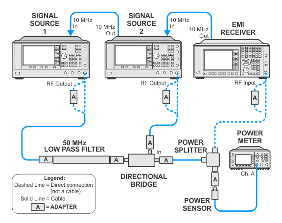
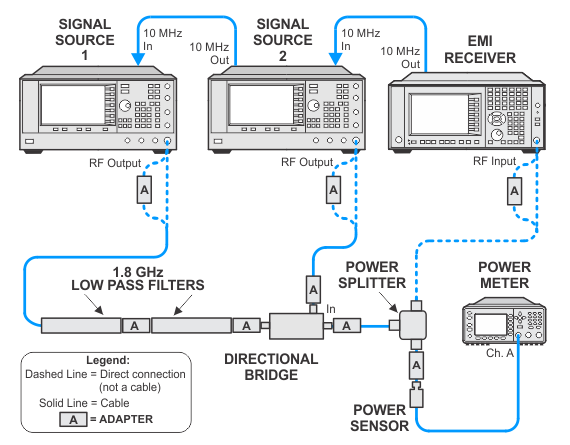
Below 3.6 GHz low-pass filters are used to attenuate the source second harmonic. The harmonic is filtered so it does not create a false failure. Above 3.6 GHz the internal YTF filters the source harmonic.
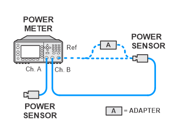
The filtered source is turned on and the signal level is measured at the splitter output port with a power meter. The filtered source amplitude is measured on the DUT. The unfiltered source is turned on and its amplitude is measured on the DUT using the DUT's delta-marker feature. The amplitude of the distortion product is then measured relative to the unfiltered source amplitude.
Click here for troubleshooting.
|
Test Equipment |
Model Number1 |
|---|---|
|
Microwave Signal Generator #1 and |
PSG Models |
|
Power Meter |
N1914A |
|
RF Power Sensor |
E9304A Option H18 |
|
Microwave Power Splitter |
11667B |
|
Millimeter Power Sensor
|
N8487A CFT |
|
Millimeter Power Splitter
|
11667C |
|
Directional Bridge |
86205A |
|
Directional Coupler |
87300B |
|
Millimeter Directional Coupler
|
87301C |
|
10 dB Fixed Attenuator |
8493C Option 010 |
|
10 dB Fixed Attenuator
|
8490D Option 010 |
|
Cable, BNC
|
8120-1840 |
|
Cable, coaxial, 3.5 mm
|
11500E |
|
Cable, coaxial, 2.4 mm
|
8120-6164 |
|
Low pass filter, 50 MHz |
Telonic Berkeley TLA 50-5AB2 |
|
Low pass filter, 1.8 GHz
|
RLC L-1636 |
|
Adapter, 3.5 mm (f) to 3.5 mm (f)
|
83059B |
|
Adapter, BNC (m) to SMA (f) |
1250-1700 |
|
Adapter, Type-N (f) to 3.5 mm (m) |
1250-1750 |
|
Adapter, Type-N (m) to BNC (f) |
1250-1476 |
|
Adapter, Type-N (m) to 3.5 mm (m) |
1250-1743 |
|
Adapter, Type-N (m) to 3.5 mm (f)
|
1250-1744 |
|
Adapter, 3.5 mm (m) to 3.5 mm (m) |
83059A |
|
Adapter, 2.4 mm (f) to 3.5 mm (f)
|
11901B |
|
Adapter, 3.5 mm (m) to 2.4 mm (f)
|
11901D |
|
Adapter, 2.4 mm (m) to 2.4 mm (m)
|
11900A |
|
Adapter, 2.4 mm (f) to Type-N (m)
|
08487-60001 |
|