![]()
The validity of the performance verification measurements depends in part on required test equipment measurement accuracy. Verify proper calibration of test equipment before running tests with this software.
The following tables list the equipment required to run the performance verification tests and adjustments. The "Recommended Model" is the preferred equipment.
Not all of the listed test equipment needs to be connected to perform an individual test. To run a test, only the equipment specified for that test needs to be connected.
|
|
The validity of the performance verification measurements depends in part on required test equipment measurement accuracy. Verify proper calibration of test equipment before running tests with this software. |
|
Instrument |
Recommended Model Number |
Alternative Model Number |
||
|
Analyzers |
||||
|
Network Analyzer |
N5247B |
|
||
|
Audio Analyzer
|
U8903B |
|
||
|
Sources |
||||
|
Function Generator |
33622A |
33611A |
||
|
Counters |
||||
|
Universal Frequency Counter |
53230A |
53132A |
||
|
Meters and Sensors |
||||
|
Power Meter1 Requires a special calibration. See footnote 1. |
N1914B |
|||
|
Power Sensor4
|
8481D |
|
||
|
Power Sensor4 |
N8482A |
N8482A-CFT |
||
|
Digital Multimeter |
3458A |
34470A |
||
|
Attenuators |
||||
|
20 dB Fixed Attenuator |
8491A Option 020 |
|
||
|
30 dB Fixed Attenuator
|
11708A |
|
||
|
Miscellaneous Devices |
||||
|
Range Calibrator |
11683A Option H01 |
|
||
|
Peak Power Meter Adapter
|
N1915A |
|
||
|
Calibration Kit, Type-N |
85032F |
85032B |
||
|
10 MHz Frequency Standard |
Microsemi 5071A |
10 MHz External Reference5 |
||
|
Pulse/Data Generator |
81160A Options 002 and 660 |
81130A
|
||
|
Power Splitter
|
11667A Option H85 or H866 |
|
||
|
Power Splitter |
11667A Option 001 |
|
||
|
Cable, XLR (m) to XLR (f), 2 m
|
U8903A-103 |
|
||
|
BNC cable |
8120-2582 |
10503A |
||
|
Calibration Test cable
|
N1912-610177 |
|
||
|
Sensor cable
|
11730A |
|
||
|
Sensor cable
|
N1917A |
|||
|
Adapter, SMB (f) to BNC (f)
|
1250-1236 |
|
||
|
BNC Tee |
1250-0781 |
|
||
|
BNC (f) to Dual Banana |
1250-2277 |
|
||
|
To ensure data integrity for measurements carried out with the Test Management Environment (TME), the following verification checks are carried out at the beginning of each test run. The checks are only performed on devices that require calibration data which directly affect the test results. If you are unable to meet the calibration requirements for these devices contributing to the measurement uncertainty only, you may still produce valid reports using the standard report format option which does not contain any measurement uncertainty information.
|
|
You are still required to enter calibration factors other than the default, but uncertainty related data is not required to produce standard format reports. |
The following table lists the standard checks performed by default:
|
Device |
Parameter Name and Description |
Limits |
A Failure Affects: |
| Power Sensor | CalFactor
(%)
The calibration factor, as a percentage |
Must be ≥10% and ≤150% at all points
|
All tests that require a power sensor |
| Uncertainty
(%)a
The uncertainty of the calibration factor, as a percentage |
Must be >0 and ≤10% at all points | Tests that require a power sensor are also guard-banded by measurement uncertainty | |
| Reflection
Coefficient Magnitude
The magnitude of the reflection coefficient |
Must be >0 and <0.5 at all points | Tests that require a power sensor are also guard-banded by measurement uncertainty | |
|
Power Splitter |
Source
Match
The magnitude of the equivalent source match |
Must be > 0 and ≤ 0.01 at 50 MHz | VSWR Calibration utility |
|
|
|
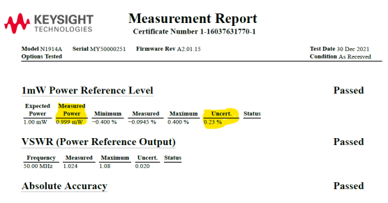
The following standard checks are performed at the beginning of the 1 mW Power Reference Level Performance Test and 1 mW Power Reference Adjustment. Note that although allowed as alternative models, E4419A and E4419B power meters are not recommended as test equipment due to higher than desired maximum measurement uncertainty levels. These power meters can have a maximum uncertainty of 0.3%. The desired maximum uncertainty of the reference power meter used in the 1 mW Power Reference Level test and adjustment should be ≤ 0.25%.
|
Device |
Parameter Name and Description |
Limits |
A Failure Affects: |
| Power Meter | Output Power (mW)
The 1 mW reference output power |
Must be ≥0.99 mW and ≤1.01 mW
|
1 mW Power Reference Level Performance Test and 1 mW Power Reference Adjustment |
| Uncertainty
(+/-) (mW)
The uncertainty of the output power, in absolute value |
Must be ≥0.0015 mW and ≤0.0035 mW | 1 mW Power Reference Level Performance Test and 1 mW Power Reference Adjustment |
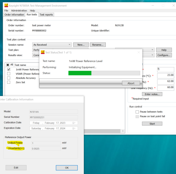
Prior to running the 1 mW Power Reference Level Performance Test and 1 mW Power Reference Adjustment, you are required to enter the 1 mW reference output power and the calibration uncertainty of the power meter used as the test equipment in the performance test and adjustment mentioned. This calibration information is required rather than the default information to be able to proceed with this test and adjustment.
Below is a sample of a measurement report from a Keysight lab. Note that these are sample values and reports may look different from calibration labs other than Keysight.
When the 1 mW Power Reference Level test and adjustment starts, TME will show the Enter Calibration Information dialog. Enter the reference output power and uncertainty values from the report into the dialog.
