Failure to follow proper test procedures may result in damage to the PNA mm-Wave system.
This is a functional test that will perform an LO calibration verification on the PNA mm-Wave system.
For each port, the nominal power is set and the test loops through 201 test points with equally spaced frequencies ranging from 10 MHz to 26.5 GHz, taking power readings at each frequency. The power readings are compared to upper and lower limits and an overall outcome of either Complete or Fail is reported.
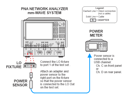
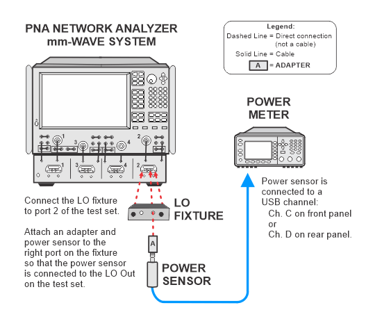
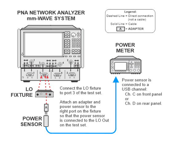
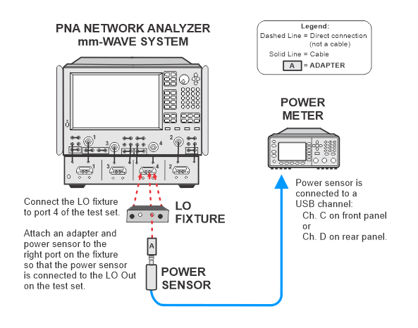
A test fixture will act as an adapter so that the power sensor can be connected directly to the ports on the test set controller bypassing the frequency extender heads.
This test requires specific procedures performed in a specific order. Please read through the following procedures before starting the test to become familiar with the sequence.
|
|
Failure to follow proper test procedures may result in damage to the PNA mm-Wave system. |
Start the LO Cal Verification test in TME. Allow the test to reach the first connection prompt.
Turn off the millimeter head controller (test set).
|
|
The test set MUST be turned OFF before removing the frequency extender heads. Failure to do so will damage the mm-Wave system. |
Close the PNA application.
Remove all of the frequency extender heads from the test set (two heads for 2-port systems; four heads for 4-port systems).
Attach the LO test fixture to the test set port. Refer to the illustrations below.
Turn on the test set.
Restart the PNA application and enable the mm-Wave system.
Resume the test in TME.
|
|
If the test fails, run the LO Cal adjustment from the PNA service adjustments. To access the service adjustments on the PNA: Utility > System > Service > Adjustment Routines... Refer to the PNA Help for more information. |
When the test has completed, follow these steps:
Turn off the millimeter head controller (test set).
|
|
The test set MUST be turned OFF before re-attaching the frequency extender heads. Failure to do so will damage the mm-Wave system. |
Close the PNA application.
Remove the LO test fixture from the test set.
Re-attach the frequency extender heads to the test set.
Turn on the test set.
Restart the PNA application and enable the mm-Wave system.
|
1 mm Connector Models |
|
|
Test Equipment1 |
Recommended Model |
|
Power meter |
N1914B |
|
PowerSensor 1 |
U8489A2 Option 200 |
|
LO test fixture |
N5292-60127 |
|
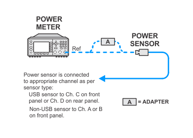
This test will use flexible power sensor channel assignment that will identify the channel that a power sensor is connected to using the ability of "smart" sensors such as the N848xA and U848xA series to report their full model and serial number. Therefore it is important to keep the power sensor on the channel where it was calibrated throughout the test procedures.
For default front and rear cabling between the PNA and the test set, refer to Step 2: Prepare the PNA for Testing of the Getting Started Guide.