Getting Started Guide
The Keysight N7840A performance test software provides fast and accurate
testing of the Keysight PNA series network analyzers. This guide should
be used in conjunction with the Test Management Environment (TME) Help. This guide provides information specific to testing PNAs using the N7840A software. Perform the steps in the order listed below.
-
Check software configuration and test equipment
-
Prepare the PNA for testing
-
Default cable connections for mm-wave PNA systems
-
Pretest the PNA
-
Run the performance tests
-
View test reports
-
Final steps
Step 1: Check Software Configuration and Test Equipment
Refer to the TME Help as needed when following the steps below:
-
Ensure that the N7840A software has been properly
installed on the controller PC (see readme.txt for N7840A for details).
-
Ensure that you have the correct test equipment for the PNA model to be tested.
-
Ensure the test equipment has been configured into
the appropriate test station under TME.
-
Ensure the required GPIB test equipment is connected
to the controller PC. If there are problems with the GPIB connections, see GPIB Troubleshooting.
Typical GPIB address configurations for the equipment in a test station are:
|
PNA
|
16
|
|
|
Signal Source
|
19
|
|
|
Power Meter
|
13
|
|
|
Frequency Counter
|
3
|
|
|
Dynamic Accuracy Test Set
|
9
|
U3020AD01
|
|
Dynamic Accuracy Test Set
|
12
|
Z5623AH01
|
|
Gain Compression Test Set
|
17
|
Z5623AK01
|
|
Gain Compression Test Set
|
23
|
U3070AK01
|
|

|
-
Be sure that an undetectable option has been indicated for the power meter if it applies. Option G12 or H12 is no longer required for the power meter used for the Dynamic Accuracy Test.
-
If a house standard (i.e. external frequency standard) is being used, be sure the test station is configured for it. See the Frequency Reference Explanation in the Frequency Accuracy Test.
|
Step 2: Prepare the PNA for Testing
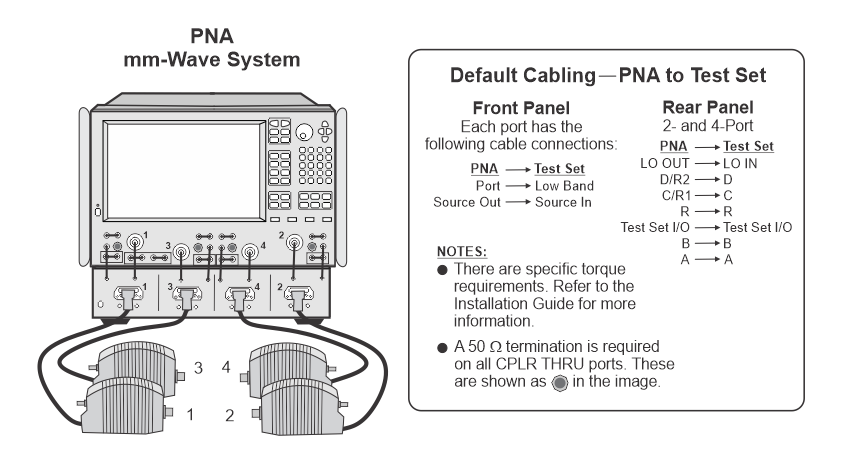
Default cable connections for mm-wave PNA systems (N5290A, N5291A)
Banded millimeter-wave systems are made up of three types of major components: a PNA or PNA-X, a controller test set, and millimeter-wave heads (frequency extenders). The millimeter head controllers provide the test
interface between the millimeter-wave test head modules and the PNA/PNA-X
(PNA) series network analyzers.
For testing to be successful, the front and rear default cable connections between the PNA and the test set must be done properly. Complete installation instructions with illustrations can be found in the N5290A/N5291A Installation Guide on the Keysight PNA technical support website. Enter the model number and click  .
.
|

|
There are specific torque requirements for the cable connections between the PNA and the test set and frequency heads. Refer to the N5290A/N5291A Installation Guide on the Keysight PNA technical support website for complete instructions.
|
Test fixture for mm-wave PNA systems (N5290A, N5291A)
For tests that have a connection from one frequency extender to another (e.g. Trace Noise Performance Test), it is recommended to use a test fixture (also called desktop positioner) to align the two frequency extenders for best test results. Refer to the Test Equipment for 1 mm Connector mm-Wave PNA Systems for the part number.
It's also helpful to use a straight edge of some sort to further align the frequency extenders. For an image of the test fixture setup, click here.
Serial number for N5290A, N5291A mmWave systems
|
Factory configured
mmWave systems
|
TME autodetect will now detect the serial number instead of having to manually enter it. For factory configured systems, the serial number may or may not already be on the PNA flash depending on the ship date of the system. During autodetect, TME will check if the serial number is on the PNA flash. If it's not, TME will instruct the user to run a PNA utility that will write the serial number to the PNA flash so that TME can detect it.
|
|
Customer configured
mmWave systems
|
Customer configured mmWave systems are now supported in TME. For its serial number, TME will automatically generate a unique ID based on the custom configuration and save it to the PNA flash. This number will be in the format of a 12-digit alpha-numeric hash code starting with the letter M, such as M12345678901. This 12-digit number will appear as the serial number on TME reports.
|
Check the basic operation of the PNA
Follow these steps before testing the PNA:
-
If the front panel loop option is installed, make sure all
loops are installed correctly. The loops are vertical on RF PNAs and
horizontal on microwave PNAs.
-
On the rear panel:
- Remove all RF, IF, and bias tee input connections.
-
Remove all control cables connected to the Handler I/O, Pulse I/O, Test Set I/O, and Pwr I/O connectors.
-
Connect the keyboard and mouse before power-up. (This may
be done later.)
-
Power up the PNA and allow it to warm up for
90 minutes.
|
|
If the PNA boots up without requiring a password, continue with the next step. If a password is required, obtain it from the PNA owner.
|
-
Press the green Preset button on the PNA.
-
Check the GPIB settings on the PNA:
-
Click System > Configure > SICL/GPIB.
-
Set as Talker/Listener; leave other boxes unchecked.
-
Note the GPIB address.
-
If the GPIB address conflicts with an existing address on the test station, temporarily change the PNA address and record the original address. The original address should be restored when testing is complete.
-
You are now ready to run the pretest as described in the next section.

Step 3: Pretest the PNA
The pretest verifies that the basic PNA performance will support the
tests. The pretest checks the S11, S22, S21, and S12 raw performance of the PNA. Run the pretest before you test each PNA. The PNA should
pass the pretest before proceeding to the Performance Tests.
Pretest Procedure
|
|
For detailed instructions that relate to some of the following steps, see Detailed Operator Tasks in the TME Help system.
|
Click Run tab to access the run screen. From the run screen, follow these steps:
-
Connect the PNA to the test station via GPIB.
-
Create a new order or open an existing order under TME for the PNA to be tested.
-
Click the Run Tests tab, indicate a Session
Name, select Utilities as the Test Plan, and select a Test
Station.
-
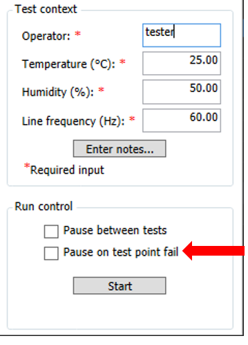
Enter the operator's name along with values for the temperature,
humidity, and line frequency in the Test Context area.
-
Click the Start button. This starts execution
of the Performance Check test.
-
Follow the setup instructions on the PC display.
-
Follow any instructions on the PC display to fix
any problems the Pretest discovers.
Pass or fail results will be indicated in the Results column. If the PNA fails one or more of the checks, see Pre-Test Failure Troubleshooting.
|
|
-
Pretest results are only
displayed temporarily as the test executes; the software does not create
a report for later reference.
-
Utilities Test Plan no longer applies to new PNA, PNA-L, and PNA-X models.
|
Step 4: Run the Performance Tests
When you have completed setting up your test station and running the
pretest from the previous section, you are ready to run the performance
tests on the PNA. If you have not already done so, click the Run Tests tab.
Procedure to run a test plan
The system is ready to test your unit. It is recommended that you perform
the pretest described above if you have not done so already.
|
|
For detailed instructions that relate to some of the following steps, see Run Tests under Detailed Operator Tasks in
the TME Help system. Normal PNA testing is done
under Performance Verification.
|
-
Select the Session Name, select Performance Verification
as the Test Plan, and select the Test Station. Next, select a Variant. As of the E.18.00 release, there are now two test plan variants available: Normal and Factory Recommended. For more information about test plan variants, refer to the Test Plan Variants topic.
-
Be sure the information in the Test Context area is correct.
-
It is recommended to check the Pause between tests
check box (in the Run Control area).
-
Be sure that  Pause on test point fail is not selected for the following tests:
-
Execute tests as desired.
If the tests do not complete successfully or if the PNA fails one or
more performance tests, see Troubleshooting Overview.
Notes on checking a connection
Generally, when a user is prompted to make a connection during a test,
the software will make simple measurements to insure the proper connection
has been made before continuing with the test. When the measurements
indicate an improper connection, the message window is titled Possible
error in connections. The connection error message generally
describes the symptom. The user is expected to be technically competent
to determine the cause of the symptom. (Connection checking is not
always practical, such as with sliding loads, shorts.)
Step 5: View Test Reports
Test results may be viewed and printed via the Test Reports
tab on the TME screen. For detailed instructions, see Session Based Reports under Detailed
Operator Tasks in the TME Help system.
Step 6: Final Steps
At testing completion, perform the following to return the PNA to its original state.
Before powering down the PNA
If the GPIB address of the PNA has been changed for testing, restore
the original address.
It is strongly recommended that the PNA Operator's Check be performed
before returning the instrument to a user. This provides a basic
functional check to make sure that nothing has "broken" unexpectedly.
Power down the PNA
Power down the PNA before disconnecting power. It is recommended that
you do a full Windows shutdown prior to returning a PNA to a customer.
(It is just like shutting down Windows before turning off power on a desktop
PC.)
ESD Precautions
Protection against ESD (electrostatic discharge) is essential while
connecting, inspecting, or cleaning connectors attached to a static-sensitive
circuit (such as those found in test sets). Static electricity can build
up in your body and can easily damage sensitive internal circuit elements
when discharged. Static discharges too small to be felt can cause permanent
damage. Devices such as calibration components and PNAs under test can
also carry an electrostatic charge. To prevent damage to the test set,
components, and devices:
-
Always wear a
grounded wrist strap having a 1 million Ohm resistor in series with it when
handling components and devices or when making connections to the test
set.
-
Always use a grounded
antistatic mat in front of your test equipment.
-
Always wear a
heel strap when working in an area with a conductive floor. If you are
uncertain about the conductivity of your floor, wear a heel strap.