Prior to running this test, certain settings must be set on the PNA to avoid error messages and possible test failure. Refer to Maximum Leveled Power Troubleshooting for more information.
|
|
Prior to running this test, certain settings must be set on the PNA to avoid error messages and possible test failure. Refer to Maximum Leveled Power Troubleshooting for more information. |
This test measures the maximum leveled power available from the PNA source across the frequency range of the PNA, and verifies the maximum power listed in the Test Port Output – Power Range specification. The test is performed at many CW frequencies across the frequency range of the PNA.
Because of the measurement process, Sources Unleveled messages are expected on the PNA display during this test.
The measurement uncertainty for this test only applies to the power meter measurement. The measurement process does not identify the precise maximum power for a given frequency. The measured value is within a 0.1 dB window below the precise maximum power.
When the actual power is more than 5 dB above the test limit, the reported max power may be less than the actual max power. This difference is caused by the limited power range of the power sensor.
For troubleshooting help, see Maximum Leveled Power Troubleshooting.
|
1 mm Connector Models |
||
|
Test Equipment1 |
Recommended Model |
Alternate Model |
|
Power meter |
N1914B |
N1914A |
|
PowerSensor 1 |
U8489A2 Option 200 |
|
|
Adapter, 1 mm (f) to 1 mm (f) May come from 85059B cal kit. |
85059-60045 |
|
|
|
|
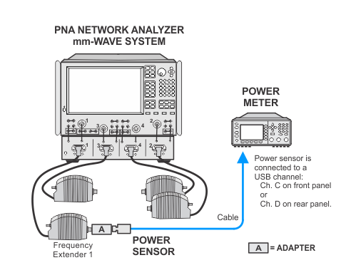
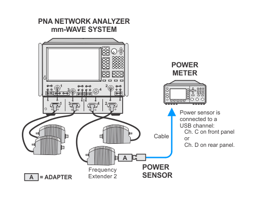
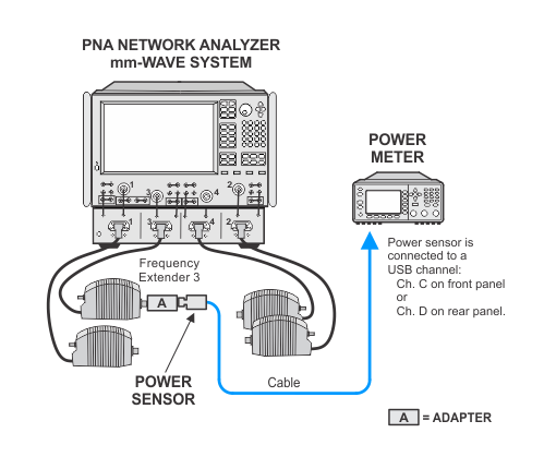
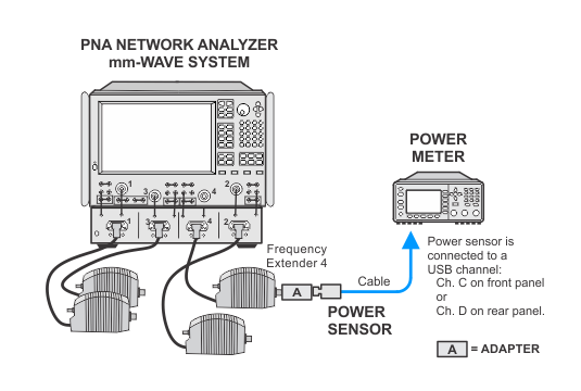
Due to the complexity of the PNA family of analyzers, the following notes apply to illustrations in the PNA Help:
|
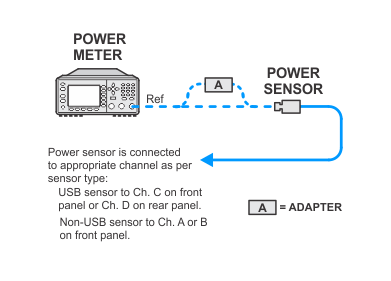
This test will use flexible power sensor channel assignment that will identify the channel that a power sensor is connected to using the ability of "smart" sensors such as the N848xA and U848xA series to report their full model and serial number. Therefore it is important to keep the power sensor on the channel where it was calibrated throughout the test procedures.
For default front and rear cabling between the PNA and the test set, refer to Step 2: Prepare the PNA for Testing of the Getting Started Guide.