Noise Receiver Compression Performance Test
This test applies to the following models:
This test is to measure the worst case compression of the RF components
of the noise receiver. The noise receiver compression is, as with all
compression, a measurement of the non-linearity of the noise receiver
at high input powers. This test has been defined to measure the compression,
or linearity, of the noise receiver at a specified input-power level relative
to a lower power level that is within the receiver’s linear range. For
this test, compression is defined as the difference between the change
in power input to the receiver and the change in power measured by the
receiver.
The PNA source will provide the power at the receiver. A pad can be
used to improve the match of the source over power. This may be required
because the noise receiver is sensitive to match changes which could happen
with input power changes. The source output power is measured and adjusted
as necessary to ensure that the appropriate test power level is injected
into the port. The source is then connected to the noise receiver port.
At each frequency the source is set to output the required power, and
a measurement is taken with the noise receiver. The power delivered
to the port is measured with the port receiver (can be frequency swept
measurement). The source power is next offset by the specified power step
(delta power) and a measurement is again taken with each receiver.
For troubleshooting help, see Noise Receiver Compression Troubleshooting.
Required Test Equipment
Below is the required test equipment separated by the DUT connector type. Select the link that applies to the connector type for your PNA model.
 Click here for 3.5 mm connector models:
N5241A/AS/B/BC, N5242A/AS/B, N5242AH85, N5249A/AS/B
-
Factory Recommended Variant, click here.
|
3.5 mm Connector Models
Factory Recommended Variant
|
|
Test Equipment1
|
Recommended Model
|
Alternate Model
|
|
Power meter
|
N1914B
|
N1914A
E4419A/B
N1912A
|
|
PowerSensor 1
|
U8485A2 Option 200
|
U8485A2
N8485A3
|
|
10 dB Fixed Attenuator, 3.5 mm
|
8493C Opt. 010
|
none
|
- Refer to the main Required Equipment table for a list of available adapters and cables.
- Requires power meter with USB ports.
- Not allowed with models with Low Frequency Extension (LFE) options.
|
-
Normal Variant, click here.
|
3.5 mm Connector Models
Normal Variant
|
|
Test Equipment
|
Recommended Model
|
Alternate Model
|
|
Power Meter
(PowerMeter1)
|
N1914A
|
E4419A/B
N1912A
EPM-442A
|
|
PowerSensor HighFreq 1
|
N8485A
|
N8485A CFT
8485A
|
|
10 dB Fixed Attenuator
(Attenuator 10dB 3.5mm)
|
8493C Opt. 010
|
none
|
|
Adapter, 3.5 mm (m) to Type-N (f)
(Adapter1 3.5mm M to N F)
|
1250-1750
|
none
|
|
RF cable, 3.5 mm (f) to 3.5 mm (f)
(RFCale 3.5mm F to 3.5mm F)
|
85131-60013
|
85131-60010
|
Click here for 2.4 mm connector models:
N5244A/AS/B, N5245A/AS/B/BC
|

|
PNA models N5244AS and N5245AS with option H29 can only use the Normal Variant.
|
-
Factory Recommended Variant, click here.
|
2.4 mm Connector Models
Factory Recommended Variant
|
|
Test Equipment1
|
Recommended Model
|
Alternate Model
|
|
Power meter
|
N1914B
|
N1914A
E4419A/B
N1912A
|
|
PowerSensor 1
|
U8488A2
|
U8487A2
N8488A3
|
|
10 dB Fixed Attenuator, 2.4 mm
|
8490D Opt. 010
|
none
|
- Refer to the main Required Equipment table for a list of available adapters and cables.
- Requires power meter with USB ports.
- Not allowed with models with Low Frequency Extension (LFE) options.
|
-
Normal Variant, click here.
|
2.4 mm Connector Models
Normal Variant
|
|
Test Equipment
|
Recommended Model
|
Alternate Model
|
|
Power Meter
(PowerMeter1)
|
N1914A
|
E4419A/B
N1912A
EPM-442A
|
|
PowerSensor HighFreq 1
|
N8487A
|
N8487A CFT
8487A
|
|
10 dB Fixed Attenuator
(Attenuator 10dB 2.4mm)
|
8490D Opt. 010
|
none
|
|
Adapter, 2.4 mm (m) to Type-N (f)
(Adapter1 2.4mm M to N F)
|
11903C
|
equivalent
|
|
RF Cable 2.4 mm (f) to 2.4 mm (f)
(RFCable1 2.4mm F to 2.4mm F)
|
85133-60016
|
85133-60002
|
Click here for 1.85 mm connector models:
N5247A/AS/B/BC
-
Factory Recommended Variant, click here.
|
1.85 mm Connector Models
Factory Recommended Variant
|
|
Test Equipment1
|
Recommended Model
|
Alternate Model
|
|
Power meter
|
N1914B
|
N1914A
E4419A/B
N1912A
|
|
PowerSensor 1
|
U8488A2
|
N8488A3
|
|
10 dB Fixed Attenuator, 1.85 mm
|
8490G Opt. 010
|
Anritsu 41V-10
|
- Refer to the main Required Equipment table for a list of available adapters and cables.
- Requires power meter with USB ports.
- Not allowed with models with Low Frequency Extension (LFE) options.
|
-
Normal Variant, click here.
|
For 1.85 mm Connector Models
Normal Variant
|
|
Test Equipment
|
Recommended Model
|
Alternate Model
|
|
Power Meter
(PowerMeter1)
|
N1914A
|
E4419A/B
N1912A
EPM-442A
|
|
PowerSensor HighFreq 1
|
N8487A
|
N8487A CFT
8487A
|
|
10 dB Fixed Attenuator
(Attenuator 10dB 1.85mm)
|
8490G Opt. 010
|
Anritsu 41V-10
|
|
Adapter, 2.4 mm F to Type-N (m)
(Adapter1 2.4mm F to N M)
|
11903D
|
equivalent
|
|
RF cable, 1.85 mm (f) to 1.85 mm (f)
(RFCable1 1.85mm F to 1.85mm F)
|
8121-2921
|
N4697-60100
|
Connection Setups
|
|
Due to the complexity of the PNA family of analyzers, the following notes apply to illustrations in the PNA Help:
- Only a single representative PNA model will be shown. Therefore, port locations may differ in older PNA models than what is shown in the illustration. Refer to the port labels on the UUT.
- Some illustrations may differ than those in TME.
- If the test procedure applies to multiple ports, illustrations may show the setup on only one test port.
- Setups for some option configurations may not appear in the Help.
|
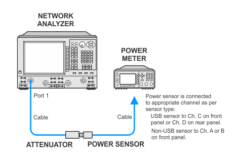
Flexible power sensor channel assignment
PNA models running the Factory Recommend Variant will use flexible power sensor channel assignment that will identify the channel that a power sensor is connected to using the ability of "smart" sensors such as the N848xA and U848xA series to report their full model and serial number. Therefore it is important to keep the power sensor on the channel where it was calibrated throughout the test procedures.
For more information about test plan variants, refer to the Test Plan Variants topic.
Calibration Source, Factory Recommended Variant
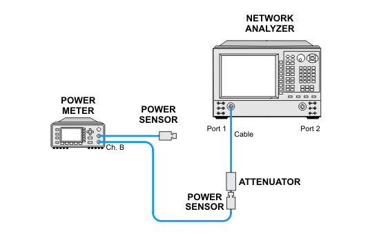
Calibration Source, Normal Variant
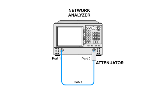
Noise Receiver Compression Measurement Setup, all variants