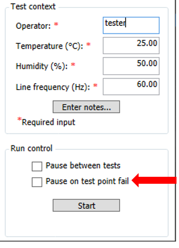
Be sure that ![]() Pause on test point fail is not selected for this test.
Pause on test point fail is not selected for this test.
N5244AS, N5245AS with Option H29
|
|
Be sure that |
There are two test plan variants available: Factory Recommended and Normal. For the Normal Variant test plan, there are also two solution choices available depending on model number: Preferred and Alternate. Equipment and connection setups will differ depending on the variant and solution. For more information about test plan variants, refer to the Test Plan Variants topic. For more information about the two solutions available in the Normal Variant test plan, go to the Noise Receiver Linearity Normal Variant Overview page.
PNA models N5244AS and N5245AS with option H29 can only use the Normal Variant.
For equipment and connection setups, select from the links below for the appropriate test plan variant:
|
|
|
Noise Receiver Linearity, as defined here, is a measure of a noise receiver's relative power linearity. It is the measurement accuracy of a noise receiver as a function of power. At a CW frequency, a signal at a known power level is delivered to the noise receiver which establishes a power reference value. The signal—at a new power level c dB from the reference—is then delivered to the receiver. As a result, the noise receiver reading will change by (X + ΔX) dB. The difference between the delta power delivered and the delta power read by the noise receiver, ΔX dB, will be the noise receiver linearity error. This process is repeated over the desired measurement range of the receiver. A mathematical expression for this specification (in dB) is:
Before the test begins, a reference power must be selected. All subsequent measurements will use the reference power for computing the noise receiver linearity error.
Two sources are used to provide the source power to the noise receiver through a special combining network. The source power at the noise receiver is adjusted to deliver a target power with one source. The power at the noise receiver is then measured with the target power applied and the other source is adjusted, using the noise receiver as the measurement device, to achieve the same power at the noise receiver.
The variation in power is achieved by placing the two sources at a specific offset frequency from one another at a specific CW frequency which, when mixed in the noise receiver, will provide a modulated power to the noise receiver at the desired CW frequency. A declared power range of this measurement is taken and the measurement is repeated with the sources set to multiple power settings to provide further range. An attenuator is also used between the combining network and the noise receiver to further extend the measurement range.
At a specified CW frequency, the noise receiver and the source make power measurements which include the reference level. As the injected signal power is stepped away from the reference level, measurements of the input signal and the noise receiver are made. For each delta power away from the reference, the above equation is used to calculate the noise receiver linearity error. The injected power is continuously adjusted away from the reference and the above process is repeated to provide the noise receiver linearity measurements over the desired dynamic range of the noise receiver.
For troubleshooting help, see Noise Receiver Linearity Troubleshooting.