Prior to running this test, certain settings must be set on the PNA to avoid error messages and possible test failure. Refer to Power Level Linearity Troubleshooting for more information.
|
|
Prior to running this test, certain settings must be set on the PNA to avoid error messages and possible test failure. Refer to Power Level Linearity Troubleshooting for more information. |
This test verifies that the power level is linear across the frequency range, and verifies the Power Sweep Range and Power Level Linearity specifications. It is performed at discrete frequencies and checks the linearity of the source over its automatic leveling control (ALC) range. It measures linearity across the specified power sweep range. The test does not check the linearity of any internal step attenuator.
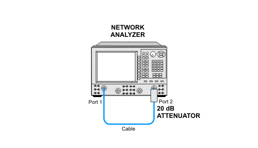
For single source PNAs, this test is only performed on port 1; therefore the specification only applies to this port. For dual source analyzers, port 3 is also tested, and the process is the same as port 1. The port 2 PNA receiver is used to test port 1. The PNA receiver linearity is the standard against which the source linearity is checked.
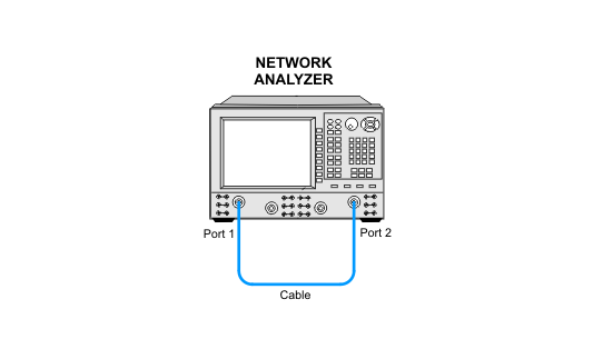
For DUTs running the Normal Variant test plan, the 20 dB attenuation during the test can come from one of two sources: the source internal step attenuator built into the PNA, or an external attenuation pad. When the internal step attenuator is used, it should be taken out of auto mode. All DUT configurations running the Factory Recommended Variant test plan must use an external fixed attenuator.
This test is performed using the Preset power level. For a list of PNA preset power levels, refer to the PNA datasheet.
For troubleshooting help, see Power Level Linearity Troubleshooting.
Below is the required test equipment separated by the DUT connector type. Select the link that applies to the connector type for your PNA model.
N5241A/AS/B/BC, N5242A/AS/B, N5242AH85, N5249A/AS/B
N5221A/AS/B, N5222A/AS/B
N5231A/AS/B, N5232A/AS/B, N5239A/AS/B
N5230A/C with option 12x, 14x, 22x, 24x, or 02x
|
3.5 mm Connector Models |
||
|
Test Equipment |
Recommended Model |
Alternate Model |
|
RF cable, 3.5 mm (f) to 3.5 mm (f) |
85131-60013 |
85131-60010 |
|
20 dB fixed attenuator1 |
8493C Opt 020 |
n/a |
|
N5244A/AS/B, N5245A/AS/B/BC
N5224A/AS/B, N5225A/AS/B
N5234A/AS/B, N5235A/AS/B
N5230A/C with option 42x or 52x
|
2.4 mm Connector Models |
||
|
Test Equipment |
Recommended Model |
Alternate Model |
|
RF cable, 2.4 mm (f) to 2.4 mm (f) |
85133-60016 |
85133-60002 |
|
20 dB fixed attenuator1 |
8490D Opt 020 |
n/a |
|
N5247A/AS/B/BC, N5227A/AS/B
|
1.85 mm Connector Models |
||
|
Test Equipment |
Recommended Model |
Alternate Model |
|
RF cable, 1.85 mm (f) to 1.85 mm (f) |
8121-2921 |
N4697-60100 |
|
20 dB fixed attenuator1 |
8490G Opt. 020 |
Anritsu 41V-20 |
|
N5290A, N5291A
|
1 mm Connector Models |
||
|
Test Equipment1 |
Recommended Model |
Alternate Model |
|
20 dB fixed attenuator, 1.85 mm |
8490G Opt. 020 |
Anritsu 41V-20 |
|
|
|
Due to the complexity of the PNA family of analyzers, the following notes apply to illustrations in the PNA Help:
|
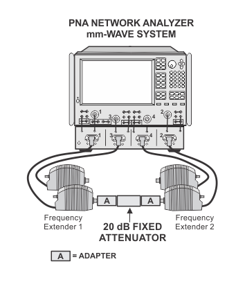
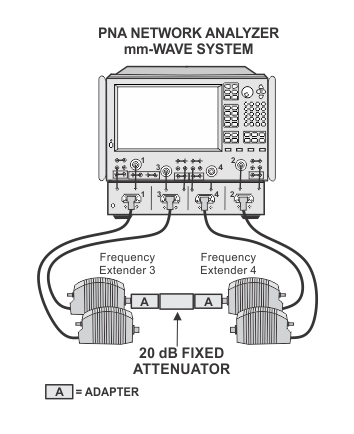
For default front and rear cabling between the PNA and the test set, refer to Step 2: Prepare the PNA for Testing of the Getting Started Guide.

|
|
An external 20 dB attenuator is required for all DUT configurations running the Factory Recommended Variant test plan. Models running the Normal Variant test plan have the option of using the internal step attenuator (if equipped). |