R-Channel Linearity Calibration
This test applies to the following models with Option 560:
|

|
This test is extremely sensitive. To minimize the chance of test failure, it is important to follow proper testing procedures:
|
R-Channel Linearity Calibration, as defined here, is to calibrate R-Channel receiver's relative power linearity. It calibrates the accuracy of a receiver as a function of power. At a CW frequency, a signal is delivered to the R-Channel receiver which establishes a power reference value. The signal—at a new power level x dB from the reference—is then delivered to the receiver. As a result, the receiver reading will change by  db. The difference between the delta power delivered and the delta power read by the receiver, Δ dB, will be the R-Channel Linearity. This process is repeated over the desired measurement range of the receiver. A mathematical expression for this specification (in dB) is:

The variation in power is achieved by placing the two sources at a specific offset frequency from one another at a specific CW frequency which, when mixed in the receiver, will provide a modulated power to the receiver at the desired CW frequency. A declared power range of this measurement is taken and the measurement is repeated with the sources set to multiple power settings to provide further range. An attenuator is also used between the combining network and the receiver to further extend the measurement range.
At a specified CW frequency, the receiver and the source make power measurements which include the reference level. As the injected signal power is stepped away from the reference level, measurements of the input signal and the receiver are made. For each delta power away from the reference, the above equation is used to calculate the linearity error. The injected power is continuously adjusted away from the reference and the above process is repeated to provide the dynamic accuracy measurements over the desired dynamic range of the receiver.
At the end of the calibrations, all linearity errors have been saved to PNA flash drive.
|

|
This calibration procedure will not change any hard specification performance of the PNA.
|
For troubleshooting help, see Dynamic Accuracy Troubleshooting since its procedure is very similar to this test.
Required Test Equipment
|
Test Equipment1
|
Recommended Model
|
|
Function generator
|
33622A
|
|
Power splitter
|
11667B
|
|
Fixed attenuator, 10 dB
(2 required)
|
8493C Option 010
|
|
Fixed attenuator, 20 dB
|
8493C Option 020
|
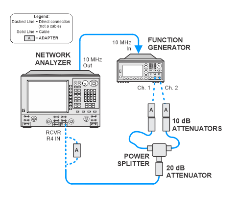
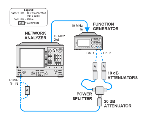
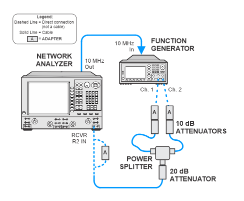
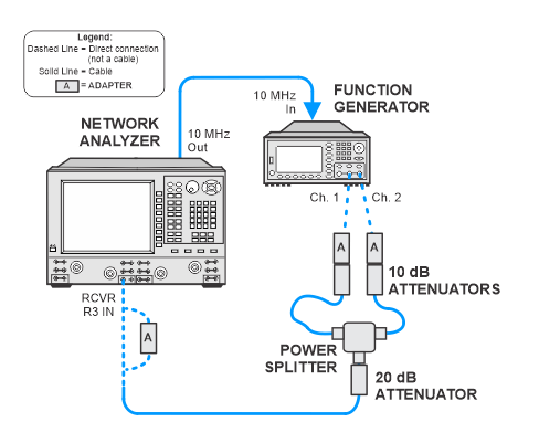
Connection Setups
|
|
For the two cables between the power splitter and attenuators, choose short but flexible cables. For best results, the cable between the attenuator on channel 1 of the function generator and power splitter should be of longer length than the cable from the attenuator on channel 2.
|
R1
R2
R3
R4