Before running this test, certain settings must be set in TME and the PNA.
For TME:
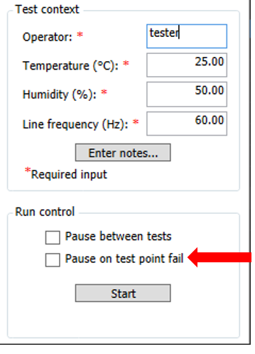
Be sure that ![]() Pause on test point fail is not selected for this test.
Pause on test point fail is not selected for this test.
For the PNA:
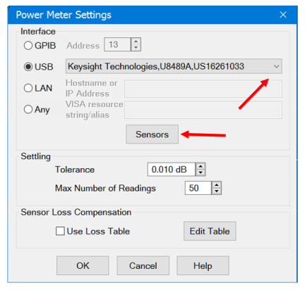
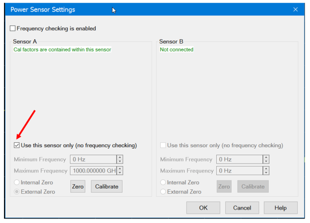
Enable power sensor setting when using USB power sensor. ![]() Click here for instructions.
Click here for instructions.