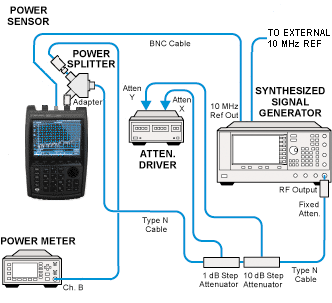
All adjustments will require the CFG Option. Refer to the CFG Option section for more information.
|
|
All adjustments will require the CFG Option. Refer to the CFG Option section for more information. |
This adjustment determines gain compensation factors for a 5 MHz span for a single frequency in each SA band. For each frequency, the source generator is held at a single CW frequency while the LO steps through 101 points to cover the 5 MHz span. The LO stepping is accomplished by special service firmware. Amplitude is measured at each point and a compensation factor is calculated.
|
Related test: |
|
Test Equipment |
Recommended Model Number |
|---|---|
|
Signal Generator #1 |
E8257D with options:
|
|
Attenuator/Switch Driver |
11713B Opt 001/024/060/101 |
|
Attenuator, 6 dB fixed |
8491A Opt 006 |
|
Attenuator, 1 dB step |
8494G Opt 001/024 |
|
Attenuator, 10 dB step |
8496G Opt 001/024 |
|
Power Meter |
N1914A |
|
Power Sensor |
E9304A Opt H18 |
|
Power Splitter |
11667A |
|
Power Sensor Cable |
11730A |
|
BNC Cable |
8120-2582 |
|
Type-N Cable |
11500C |
|
Attenuator control cable |
8120-2703 |
|
|
The following notes apply to illustrations in the FieldFox Help:
|

