Getting Started
|

|
-
N7841A calibration application versions E.04.02 and greater require a minimum version of firmware to be installed in the FieldFox to successfully run tests and adjustments. Refer to the Firmware Requirements section for more information.
-
Some FieldFox model and option combinations will require the installation of the CFG Option in order to complete tests. All adjustments will require the CFG Option. Refer to the CFG Option section for more information.
|
Before You Start
Installing Over Previous Versions
Please see the Readme.txt of TME for information on the compatibility of this
package with previous versions of the application and the Test Management
Environment (TME).
|

|
TME applications E.01.00 and later cannot be installed over older TME
applications (A.xx, C.xx, or D.xx) or on top of TME versions prior to
E.01.00. You must remove TME and all applications from the PC before installing
the latest TME and this application.
Please see the TME help, Getting Started, Installation section for details
of how to remove pre-E.01.00 versions of TME and its applications.
|
Separation of TME from Applications
Keysight TME is no longer packaged and installed with
TME applications. TME must be installed separately. Once TME is installed
on the target PC, the applications can then be installed.
Please see the TME help system and Readme for information
on installing the Keysight Test Management Environment.
System Requirements
Please see the Readme.txt for minimum system requirements to run this
application.
Installation Steps
There are two ways to install TME and its applications:
-
Network
Installations — Equipment and test data information is stored in a
central location (the TME Server). This data is shared among a set of
TME Clients. Multiple test stations can then have access to this central
information.
-
Local Installations — Everything is installed on one PC.
Installation
Network Installation
In a network installation, order information is stored centrally and
can be accessed by any TME client in the network. This allows you to combine
data from tests that were run on multiple stations into a single report.
Equipment data and order information are also accessible from any station.
To set up a new TME network, please see the instructions in the TME
help system.
|
|
-
The
installation of the application network data must take place on the same
PC that installed the TME network data.
-
If TME is setup as a network installation, the application will automatically
be setup as a network on that machine when the installation is executed.
The application server must be installed before any clients can be installed.
-
TME client must also be installed on all machines intending to run this
application as clients of the network.
|
To install an application on a network follow the following steps:
-
Find the PC where the TME network was installed (shows
“TME Server” in Programs & Features).
-
Run Setup.exe for the application on that PC. This will
install all networked components for that application.
-
Install application clients:
Or
\\FileServer\Test
Management Environment\Install\(AppName)\(AppName)ClientSetup.exe
|
|
The
client setup must be run from this location. It should not be moved or
renamed.
|
Local Installation
TME must be installed on the target PC before the application
installation can occur.
On a local installation, all application data is stored
on the target PC. Once TME has been installed as a local installation,
the application installation will automatically install locally when executed.
Order information, test results, and equipment data will not be shared
with other users.
Uninstallation
|
|
If you uninstall TME completely or uninstall any TME application,
you will lose the data associated with those applications. Create any
reports needed and save them as PDF files before you uninstall that product.
|
-
To uninstall previous versions of TME, please see Installing
over Previous Versions.
-
To uninstall TME or any TME application, select that package
from Programs & Features.
Uninstall of Network Install
To uninstall an application client, select that package from Programs & Features, and click Remove.
|
|
Data
will not be lost if only a client is uninstalled. Other clients will still
have access to the data in the network.
|
To uninstall an application server:
-
Follow the directions above to uninstall all application
clients.
-
Once all application clients have been uninstalled,
uninstall the application server from the PC where the server installation
was performed.
-
Select the application server from Programs & Features, and click Remove.
Uninstall of Local Install
To uninstall an application local installation, select that package
from Programs & Features, and click Remove.

N7841A Application Installation
|
|
-
N7841A calibration application versions E.04.02 and greater require a minimum version of firmware to be installed in the FieldFox to successfully run tests and adjustments. Refer to the Firmware Requirements section for more information.
-
Some FieldFox model and option combinations will require the installation of the CFG Option in order to complete tests. All adjustments will require the CFG Option. Refer to the CFG Option section for more information.
|
The N7841A test application must be installed on a PC with a LAN port. The LAN connection for the PC is required because the N7841A test application
communicates with the UUT via LAN. (This
does not mean the N7800A installation must be a network installation;
a local installation is acceptable.)
The N7841A test application communicates with the test equipment via
GPIB. The LAN connection for
the FieldFox analyzer is required because the UUT is not equipped with a
GPIB interface.
Check the following PC configuration:
File and Printer Sharing should be enabled on the PC running TME. On the PC:
- Select Start > Control Panel > Windows
Firewall and select the Exceptions tab.
- Check the File and Printer
Sharing box.
- Click OK.
|
|
If the PC is not configured properly, an error may be generated with DrivingDataFiles
in the filename path.
|
Connecting the FieldFox Analyzer to a LAN and Configuring the IP Address
The calibration software communicates with the FieldFox through LAN. Therefore,
the FieldFox needs to be configured for network activity.
|
|
The procedures below can be made during the UUT warm-up.
|
-
Connect the LAN cable from the LAN connector on
the side of the FieldFox to an available connector on a local area network or
directly to the TME PC. If the FieldFox is connected to a local area network, follow Step 2 below to configure the FieldFox to obtain the IP address
via DHCP. If connected directly to the TME PC, set the FieldFox for
a static IP address. A "cross over" LAN cable is not required
when making a direct connection between the FieldFox and the TME PC.
-
To configure the FieldFox to obtain an IP address
via DHCP:
-
Press System 7 > System
Configuration > MORE > LAN soft keys; press
the down arrow button to scroll down to the Obtain IP line.
-
If the value needs
to be changed, press the Edit soft key. Press the Obtain IP soft key to underline DHCP. Press Done Edit.
-
Scroll down to
the Apply Settings line.
-
Press the Edit > Apply Settings soft keys. A box should briefly
appear toward the lower right-hand corner of the display indicating File Saved:
\UserData\LanConfig.reg.
The underline in the Apply Settings
soft key should indicate PowerUp after a few seconds. If not, repeat this step. Press Done.
-
There should now be a
value for Current IP Address. If there is no value displayed,
then cycle power on the
FieldFox (hold on/off button for four seconds to turn off). This will allow
the DHCP server to assign an IP address.
-
To configure the FieldFox to use a static IP address:
-
Go to https://www.keysight.com/us/en/lib/resources/technical-specifications/telnet-communication-to-the-fieldfox-over-lan-2100789.html . Follow the
instructions for the Direct Connection option. It is recommended
to open a telnet connection between the PC and FieldFox to confirm that the
connection is established.
-
Press System
7 > System Configuration > MORE > LAN.
Record the current IP address.
Enter IP Address in TME
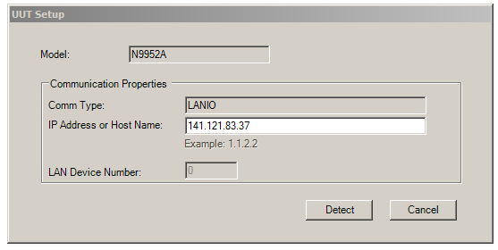
Follow the steps below to enter the FieldFox IP address in TME.
-
When creating a new order in TME, select the
model number and click the Model Info…
button.
-
In the UUT Setup
dialog box (example below), type in the IP address of the FieldFox analyzer and then click on the Detect
button.
-
After you click on the Detect
button, the information from the UUT will be displayed. After reviewing
the information and entering the desired data, press the Done
button.
-
Press Save to complete the creation of
the order.
|
|
To change the IP address for
an order after it has been saved, select File > Edit Order.... at the top of the window. Then click the Model Info....
button.
|
Connecting GPIB Test Instruments
This section describes the preparation of the instruments
used by the test software at a given test station. The test software does
not check instruments for proper operation on the GPIB bus before attempting
to perform tests.
All test equipment controlled by GPIB should be connected to the GPIB connector of the controller PC (typically GPIB0).
The typical GPIB address configuration for a test station is:
|
Signal Generator
|
19
|
|
Power Meter
|
13
|
|
Frequency
Counter
|
3
|
|
Source
|
19
|
|
Network Analyzer
|
16
|
|
DVM
|
22
|
|
Function Generator
|
10
|
|
Oscilloscope
|
4
|
It is recommended that the operator follow the steps below to manually
check for proper connection of the GPIB devices before performing tests
on a newly connected test station.
-
Note the GPIB address of each
instrument associated with the test station/test plan defined earlier.
-
Connect a power cord to each
instrument, and then connect each instrument to the computer serving as
the GPIB controller.
-
Power up all the instruments
on the GPIB bus.
-
Check each GPIB instrument for proper communication
over the bus and the required . Follow the
process described in "Checking GPIB Bus Devices" below.
Checking GPIB instruments
|
|
When checking the basic operation of each instrument or when checking
for detectable options on a given instrument, you may need to look up
the actual command for retrieving the identification string before performing
these steps.
|
-
Start the Keysight Connection Expert from the task bar or access it through Start > All Programs > Keysight Connection Expert.
-
Check for all expected GPIB devices. Verify that all expected GPIB devices are shown in the left window. If a device is missing, correct the problem and re-scan for connected instruments.
-
Check for basic operation of each GPIB device:
|
|
If an instrument does not support SCPI, refer to the user guide for
the product to learn more about checking the basic operation of its GPIB.
|
-
Select a GPIB device.
-
Select the Interactive
I/O from the right window.
-
The command window should be pre-populated with the *IDN? query. You can also select from the Commands > drop-down menu, or simply type *IDN? in the command window.
-
Select Send & Read.
-
Verify that the expected model number is contained
in the response text string.
-
Check for on a given device:
|
|
This does not work with the power meter.
|
-
Select a GPIB device to highlight it.
-
Select the Interactive
I/O from the right window.
-
Type *OPT?
in the command window.
-
Select Send & Read.
Warm-up Procedures
Ambient temperature recommended during adjustments and
tests: 20° to 26° C.
To display the temperature sensor readings on the FieldFox, press System (7) > Service Diagnostics > Internal Temperatures
Internal temperature range required for adjustments and recommended for tests:
RF1 and RF2 sensors are located on the RF PCA.
SB1 and SB2 sensors are located on the System Board PCA.
|
Model
|
Sensor
|
Temperature Range:
Firmware < A.09.00
|
Temperature Range:
Firmware ≥ A.09.00
|
|
N9923A1
|
SB2
|
43 to 55° C
|
48 to 58° C
|
|
N9912A
|
RF2, SB22
|
40 to 50° C
|
45 to 55° C
|
|
N991xA/N992xA/N993xA
|
RF2, SB22
|
43 to 55° C
|
48 to 60° C
|
|
N995xA/N996xA
|
RF2, SB22
|
N/A
|
48 to 62° C
|
|
1. Temperature range for Phaselock Accelerator Adjustment is 43° C to 53° C.
2. SB2 is only checked in the Frequency Accuracy Adjustment.
|
Typical stabilization time: 60 to 90 minutes
When positioned with an open kick stand, the internal temperature of the unit will typically
rise above ambient temperature by the following degrees:
- N9912A — 23° C
- N9923A — 29° C
-
All other — 30° C
The
temperature rise will depend on operating mode and battery charge level.
The UUT must remain in a consistent thermal environment
during warm-up, adjustments, and testing. This includes ambient air
temperature, circulation of ambient air on the unit, and physical
position of the unit (kick stand, etc). The UUT should have a battery installed and be continuously connected to external power during
warm-up, adjustment, and testing.
Warm-up Procedure
This procedure assumes the UUT is off.
-
Connect external power to the UUT, turn it on, and preset it (Preset
> Preset).
-
Position the UUT in the upright position using the built-in kick stand.
-
Allow the internal temperature to stabilize before performing any tests (less than a one
degree change in ten minutes). Typical stabilization time: 60 to 90 minutes.
-
Before performing adjustments, make sure the UUT is stabilized in the required temperature range (see above).
When the stabilized temperature is not within the required range:
-
If the temperature is too low, collapse the kick stand and
lay the UUT on its back. This should raise the internal temperature about
four degrees. An alternative is to place insulating material (foam, etc.)
against the back of the UUT under the kick stand.
-
If the temperature is too high, position a small fan to
circulate air between the kick stand and the back of the UUT. This should lower
the internal temperature about five degrees depending on the volume of
air flow.
-
Changing the display brightness will affect heating within the
UUT. Set the display to 100% brightness to dissipate maximum power in the
UUT.
-
Allow the internal temperature of the UUT to stabilize again. Confirm that the UUT is in the required temperature range before beginning
adjustments or tests.
ESD Precautions
Protection against ESD (electrostatic discharge) is essential
while connecting, inspecting, or cleaning connectors attached to a static-sensitive
circuit (such as those found in test sets). Static electricity can build
up in your body and can easily damage sensitive internal circuit elements
when discharged. Static discharges too small to be felt can cause permanent
damage. Devices such as calibration components and units under test (UUTs)
can also carry an electrostatic charge. To prevent damage to the test
set, components and devices:
-
Always
wear a grounded wrist strap having a 1 million Ohm resistor in series
with it when handling components and devices or when making connections
to the test set.
-
Always
use a grounded antistatic mat in front of your test equipment.
-
Always wear
a heel strap when working in an area with a conductive floor. If you are
uncertain about the conductivity of your floor, wear a heel strap.