Network Analyzer Calibration Procedure for Performance Tests

This test applies to the following models:

The network analyzer used in certain tests must be calibrated with the cable and adapter prior to running the test. The calibration will need to be repeated once every three days or if the adapters or cables have been disturbed. If it's been within the three day time-frame and the adapters and cables have not been disturbed, then the network analyzer calibration is not necessary and you may proceed with the test.

There are two calibration procedures used. These procedures are located in the Utilities Test Plan in TME. They are also embedded in the individual tests that require the network analyzer calibration procedure.


Required Test Equipment

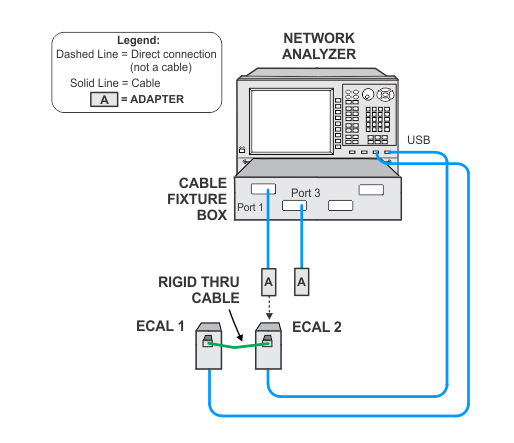
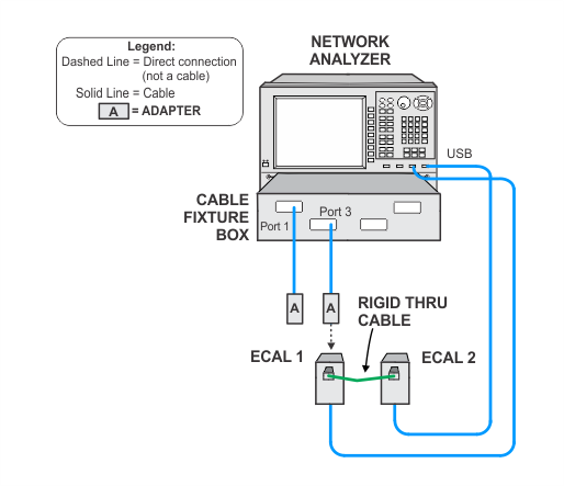
  • Due to the sensitivity of this calibration, use good quality cables and adapters, minimize cable movement, and avoid bending the cables unnecessarily. It is recommended that you clean the cable ends and adapters before attaching to the network analyzer.

  • The network analyzer calibration procedures are performed within an Optimized Test Station. See Optimized Test Station for more information.

Test Equipment

Recommended Model1

Optimized Test Station

The Optimized Test Station consists of an equipment rack with a specialized cable fixture box and other components such as a PNA-X network analyzer, ECals, power sensors, cables, and adapters. Testing must be performed within this custom test station which are only available at a limited number of Keysight service centers. See Optimized Test Station for more information.

Network analyzer

N5247B with options:

  • 425
  • 560: R-channel calibration option
  • S93080B: frequency offset

Power meter

N1914A

Power sensor, 1.85 mm

N8488A

ECal module, 2.4 mm

  • 2 required

N4693D Options 0DC, M0F

ECal module, 1.85 mm

  • Used as ECal-3 to characterize the 2.4 mm (m) to 1.85 mm (f) adapter that is used with the power sensor

N4694D Option M0F

Barrel adapter, 2.4 mm (f) to 2.4 mm (f)

  • 2 required

11900B

Adapter, 2.4 mm (m) to 1.85 mm (f)

  • Used with power sensor


Cable, 1.85 mm (f) to 1.85 mm (m)

  • 2 required

Rigid thru cable

ET55861-0003

  1. Refer to the main Required Test Equipment table for a list of alternative models.

PNA and Power Meter Setup

The power meter used in these procedures will be controlled by the network analyzer through the GPIB connection from the power meter to the network analyzer. Therefore the power meter needs to be added to the Keysight Connection expert via a remote GPIB interface.

The following steps will explain how to configure the PNA and the power meter's remote GPIB interface.

When using an NI IO card or NI USB-to-GPIB converter, be sure that the NI-VISA Passport for Tulip has been enabled to recognize and detect Keysight hardware. Refer to the following document for more detailed troubleshooting instructions: http://literature.cdn.keysight.com/litweb/pdf/5990-3731EN.pdf

  1. Ensure that Remote IO Server is enabled on the PNA.

    1. From the PNA front panel, exit the PNA application: File > Exit.
    2. From the PNA front panel, run Keysight Connection Expert.
    3. Click on the gear in the upper-right, then select Settings > Remote IO Server options. Ensure Enable Remoter IO Server and Auto-Start Remote IO Servers on Machine Setup are selected.

    4. Close Keysight Connection Expert, and restart the Network Analyzer application by double clicking on the shortcut from the PNA front panel.

  2. Make the GPIB cable connections so that the PNA can control the power meter.

    1. Connect the GPIB cable from the PNA GPIB (1) TALKER/LISTENER to the GPIB Bus on the PC.
    2. Connect the GPIB cable from the PNA GPIB (0) CONTROLLER to the power meter.

  3. Configure the remote GPIB interface on the PC and in TME.

    1. Launch Keysight Connection Expert on your PC. Click on the +Add and the select Remote GPIB interface.
    2. Enter the IP Address of the PNA. To obtain the IP Address, from the PNA front panel, go to Utility > System > System Setup > LAN Status….
    3. Click on Test Connection to verify that the connection was made.

  4. In Keysight Connection Expert, you should now see the remote GPIB interface you have created, and the power meter that is connected (by GPIB) to the controller of the PNA.

  5. Now in TME Station Administration, map the power meter to the appropriate board and address. Using the example above, the correct board is 3 and the address is 13.

Network Analyzer Frequency Sweep Calibration

This procedure performs CAL ALL on multiple frequency sweep channels with different source attenuation on the network analyzer.

Click on the links below for connection setup images. To expand all, click the Expand All button in the toolbar (webhelp only).

  1. ClosedClick here for power sensor calibration.


  2. ClosedClick here for power calibration.


  3. ClosedClick here for adapter characterization.


  4. ClosedClick here for s-parameter calibration.


  5. ClosedClick here for s-parameter calibration verification.


  6. ClosedClick here for verification power sensor calibration.


  7. ClosedClick here for power verification.


Network Analyzer Power Sweep Calibration

This procedure performs CAL ALL on multiple power sweep channels with different source and receiver attenuation on the network analyzer.

Click on the links below for connection setup images. To expand all, click the Expand All button in the toolbar (webhelp only).

  1. ClosedClick here for power sensor calibration.


  2. ClosedClick here for power calibration.


  3. ClosedClick here for adapter characterization.


  4. ClosedClick here for s-parameter calibration.


  5. ClosedClick here for s-parameter calibration verification.