Dynamic Accuracy Performance Test — Alternate Solution
|

|
- Because of the sensitivity of this test, it is recommended to leave the power sensor undisturbed and connected to the Dynamic Test Set for at least 30 minutes prior to running the test.
- Dynamic accuracy above 0 dBm is not checked by this test. It is checked by the Receiver Compression test.
|
Dual Solution Test
There are two solutions available for this test depending on the test equipment mapped in TME.
TME will select the solution depending on the ETE that is mapped. If both test sets and the signal generator are mapped, TME will run the preferred solution with the U3020A-D01 test set and signal generator. If only the Z5623A-H01 test set is mapped, TME will run the alternate solution. For the preferred solution, click here.
Test Description
This test measures the relative power linearity of the network analyzer's receivers, and verifies the Test Port Input – Dynamic Accuracy specification.
All measurements are performed at 1.195 GHz with the
PNA in CW mode. Each port is tested separately. The reference power level for measurements is -22 dBm.
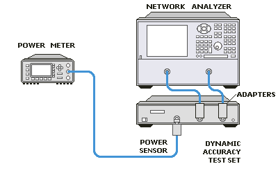
The Dynamic Accuracy Test Set (Z5623A Option H01) is used
in the test. It inputs a signal from a source port on the PNA. The input
signal is routed through step attenuators to both the PNA port under test
and the power sensor (N8482A or 8482A).
The test process is very complex. It uses the PNA source
and the Dynamic Accuracy Test Set to create power levels that are deltas
from the reference power level (-22 dBm). Each delta is measured two ways: by the power sensor and by the PNA receiver under test.
The power measurements made by the power
sensor are limited to the nominal range of -2 to -12 dBm. The power sensor
is very linear and repeatable in this limited range. The power output
level of the PNA and the step attenuators in the Dynamic Accuracy Test
Set are manipulated to meet this requirement. Typically, multiple power
sensor readings are "stacked up" (combined) to determine the
magnitude of a single delta measurement.
When a PNA receiver measures a power level, the following conditions
apply:
-
The averaging is dependent on the power level. Lower
power levels require higher averages. Up to 64 averages can be used for
the lowest power levels.
-
IFBW=100 Hz
-
51 points per sweep
-
Two measurements are made simultaneously, a ratioed
thru measurement (B/R, A/R, and so forth) in linear format and a reference
(R) measurement in watts. The ratio measurement allows the instrument
to perform the averaging more accurately.
-
After the appropriate number of sweeps have been
averaged, the mean trace statistic is used to determine two separate values:
the ratioed measurement (no units) and the reference measurement (watts).
To determine the average power measured by the non-reference receiver
in watts, multiply the ratioed measurement by the reference measurement.
(Example: [A/R] * [R]= A)
-
Watts are converted to dBm (Pdbm= 10 * Log 10(Watts * 1000) )
For troubleshooting help, see Dynamic Accuracy Troubleshooting.
Required Test Equipment
Below is the required test equipment for this test. Select the link that applies to your model.

|
Test Equipment — Table A
PNA RF Models:
E8356A, E8357A, E8358A
E8801A, E8802A, E8803A
|
|
Test Equipment
|
Recommended Model
|
Alternate Model
|
|
Power meter
|
N1914A
|
E4419A/B
EPM-442A
N1912A
|
|
Power sensor
|
N8482A
|
8482A
|
|
Dynamic Accuracy Test Set
|
Z5623A-H01
|
none
|
|
Adapter Type-N (m) to Type-N (m)
|
1250-0778
|
equivalent
|
|
RF cable Type-N (m) to Type-N (m)
(qty. 2)
|
N6314A
|
8120-8862
|
|
Power sensor cable
|
11730A
|
equivalent
|
| |
|
Test Equipment — Table B
PNA Microwave Analyzers:
E8362A, E8362B, E8362C
|
|
Test Equipment
|
Recommended Model
|
Alternate Model
|
|
Power meter
|
N1914A
|
E4419A/B
EPM-442A
N1912A
|
|
Power sensor
|
N8482A
|
8482A
|
|
Dynamic Accuracy Test Set
|
Z5623A-H01
|
none
|
|
Adapter 3.5 mm (m) to Type-N (m)
(qty. 2)
|
1250-1743
|
equivalent
|
|
RF cable 3.5 mm (f) to 3.5 mm (f)
(qty. 2)
|
85131-60013
|
85131-60010
(not for 4 port)
|
|
Power sensor cable
|
11730A
|
equivalent
|
|
|
|
Test Equipment — Table C
PNA Microwave Analyzers:
E8363A, E8363B, E8363C
E8364A, E8364B, E8364C
E8361A, E8361C
|
|
Test Equipment
|
Recommended Model
|
Alternate Model
|
|
Power meter
|
N1914A
|
E4419A/B
EPM-442A
N1912A
|
|
Power sensor
|
N8482A
|
8482A
|
|
Dynamic Accuracy Test Set
|
Z5623A-H01
|
none
|
|
Adapter 2.4 mm (m) to Type-N (m)
(qty. 2)
|
11903A
|
equivalent
|
|
RF cable 2.4 mm (f) to 2.4 mm (f)
(qty. 2)
|
85133-60016
N4697-60100
|
85133-60002
(less flexible)
|
|
Power sensor cable
|
11730A
|
equivalent
|
Connection Setups
|
|
Due to the complexity of the PNA family of analyzers, the following notes apply to illustrations in the PNA Help:
- Only a single representative model will be shown.
- Some illustrations may differ than those in TME.
- For procedures that apply to multiple ports, illustrations will show the setup on only one test port.
|
Dynamic Accuracy Measurement Setup