Dynamic Accuracy Performance Test — Preferred Solution
|

|
This test is extremely sensitive. To minimize the chance of test failure, it is important to follow proper testing procedures:
- Ensure all connectors are clean.
- Properly torque all connections.
- Check that all test equipment is attached to the correct connecter and has solid connections.
- Ensure that the required equipment is being used.
|
|

|
- Because of the sensitivity of this test, it is recommended to leave the power sensor undisturbed and connected to the Dynamic Test Set for at least 30 minutes prior to running the test.
- Dynamic accuracy above 0 dBm is not checked by this test. It is checked by the Receiver Compression test.
|
Dual Solution Test
There are two solutions available for this test depending on the test equipment mapped in TME.
TME will select the solution depending on the ETE that is mapped. If both test sets and the signal generator are mapped, TME will run the preferred solution with the U3020A-D01 test set and signal generator. If only the Z5623A-H01 test set is mapped, TME will run the alternate solution. For the alternate solution, click here.
Test Description
Dynamic Accuracy, as defined here, is a measure of a receiver's relative power linearity. It is the measurement accuracy of a receiver as a function of power. At a CW frequency, a signal at a known power level is delivered to the receiver which establishes a power reference value. The signal—at a new power level x dB from the reference—is then delivered to the receiver. As a result, the receiver reading will change by ( ) db. The difference between the delta power delivered and the delta power read by the receiver,
  dB, will be the dynamic accuracy error. This process is repeated over the desired measurement range of the receiver. A mathematical expression for this specification (in dB) is:

Before the test begins, a reference power must be selected. All subsequent measurements will use the reference power for computing the dynamic accuracy error. The reference power is normally selected somewhere well above the noise floor and safely below source and receiver compression.
Two sources are used to provide the source power to the receiver through a special combining network. The source power at the receiver is adjusted to deliver a target power with one source. The power at the receiver is then measured with the target power applied and the other source is adjusted, using the receiver as the measurement device, to achieve the same power at the receiver.
The variation in power is achieved by placing the two sources at a specific offset frequency from one another at a specific CW frequency which, when mixed in the receiver, will provide a modulated power to the receiver at the desired CW frequency. A declared power range of this measurement is taken and the measurement is repeated with the sources set to multiple power settings to provide further range. An attenuator is also used between the combining network and the receiver to further extend the measurement range.
At a specified CW frequency, the receiver and the source make power measurements which include the reference level. As the injected signal power is stepped away from the reference level, measurements of the input signal and the receiver are made. For each delta power away from the reference, the above equation is used to calculate the dynamic accuracy error. The injected power is continuously adjusted away from the reference and the above process is repeated to provide the dynamic accuracy measurements over the desired dynamic range of the receiver.
For troubleshooting help, see Dynamic Accuracy Troubleshooting.
Required Test Equipment
Below is the required test equipment for this test. Select the link that applies to your model.

|
Test Equipment — Table A
PNA RF Models:
E8356A, E8357A, E8358A
E8801A, E8802A, E8803A
|
|
Test Equipment
|
Recommended Model
|
Alternate Model
|
|
Power meter
|
N1914A
|
E4419A/B
EPM-442A
N1912A
|
|
Power sensor
|
N8482A
|
8482A
|
|
Dynamic Accuracy Test Set
|
U3020A-D01
|
none
|
|
Signal Generator
Used with the U3020A-D01 test set.
|
E8257D
|
N5182B
E8257C
E8267C/D
|
|
Load 3.5 mm (m)
Used with the U3020A-D01 test set.
May come from 85058B cal kit.
|
909D
|
902C
|
|
Adapter Type-N (m) to Type-N (m)
|
1250-0778
|
equivalent
|
|
RF cable Type-N (m) to Type-N (m)
(qty. 2)
|
N6314A
|
8120-8862
|
|
Power sensor cable
|
11730A
|
equivalent
|
| |
|
Test Equipment — Table B
PNA Microwave Analyzers:
E8362A, E8362B, E8362C
|
|
Test Equipment
|
Recommended Model
|
Alternate Model
|
|
Power meter
|
N1914A
|
E4419A/B
EPM-442A
N1912A
|
|
Power sensor
|
N8482A
|
8482A
|
|
Dynamic Accuracy Test Set
|
U3020A-D01
|
none
|
|
Signal Generator
Used with the U3020A-D01 test set.
|
E8257D
|
N5182B
E8257C
E8267C/D
|
|
Load 3.5 mm (m)
Used with the U3020A-D01 test set.
May come from 85058B cal kit.
|
909D
|
902C
|
|
Adapter 3.5 mm (m) to Type-N (m)
(qty. 2)
|
1250-1743
|
equivalent
|
|
RF cable 3.5 mm (f) to 3.5 mm (f)
(qty. 2)
|
85131-60013
|
85131-60010
(not for 4 port)
|
|
Power sensor cable
|
11730A
|
equivalent
|
|
|
|
Test Equipment — Table C
PNA Microwave Analyzers:
E8363A, E8363B, E8363C
E8364A, E8364B, E8364C
E8361A, E8361C
|
|
Test Equipment
|
Recommended Model
|
Alternate Model
|
|
Power meter
|
N1914A
|
E4419A/B
EPM-442A
N1912A
|
|
Power sensor
|
N8482A
|
8482A
|
|
Dynamic Accuracy Test Set
|
U3020A-D01
|
none
|
|
Signal Generator
Used with the U3020A-D01 test set.
|
E8257D
|
N5182B
E8257C
E8267C/D
|
|
Load 3.5 mm (m)
Used with the U3020A-D01 test set.
May come from 85058B cal kit.
|
909D
|
902C
|
|
Adapter 2.4 mm (m) to Type-N (m)
(qty. 2)
|
11903A
|
equivalent
|
|
RF cable 2.4 mm (f) to 2.4 mm (f)
(qty. 2)
|
85133-60016
N4697-60100
|
85133-60002
(less flexible)
|
|
Power sensor cable
|
11730A
|
equivalent
|
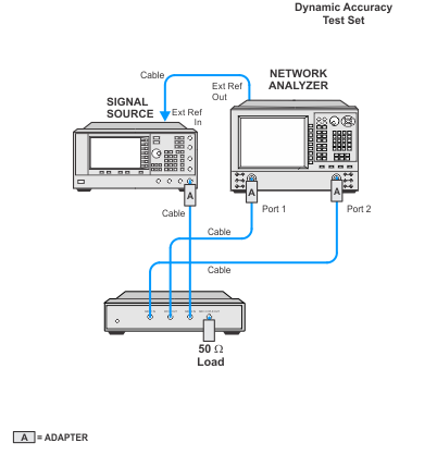
Connection Setups
|
|
Due to the complexity of the PNA family of analyzers, the following notes apply to illustrations in the PNA Help:
- Only a single representative model will be shown.
- Some illustrations may differ than those in TME.
- For procedures that apply to multiple ports, illustrations will show the setup on only one test port.
|
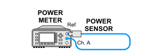
Power Sensor Calibration Setup
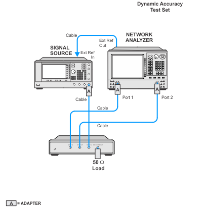
Source Calibration
Dynamic Accuracy Measurement Setup