
The VSWR test should be run prior to running this test.
|
|
The VSWR test should be run prior to running this test. |
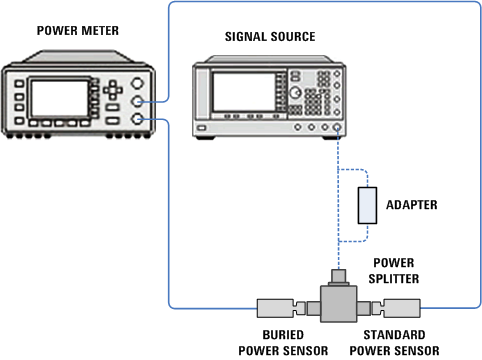
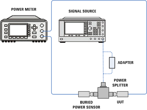
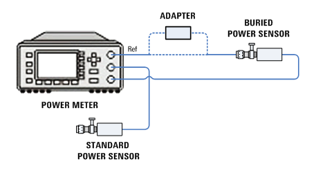
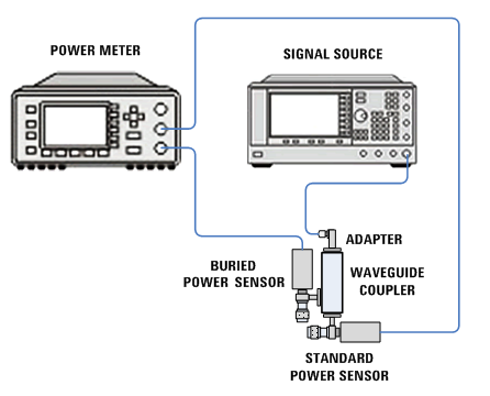
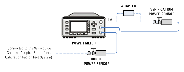
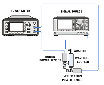
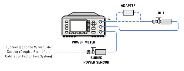
The purpose of this test is to characterize the calibration factor of the power sensor at each frequency parameter. The calibration factor created will be used as the correction for the power measured.
A text file of the measured calibration factors will be generated in:
C:\Documents and Settings\All Users\Application Data\Agilent Technologies\Test Management Environment\{PowerSensorFamily}\{Model#}_{Serial#}.txt
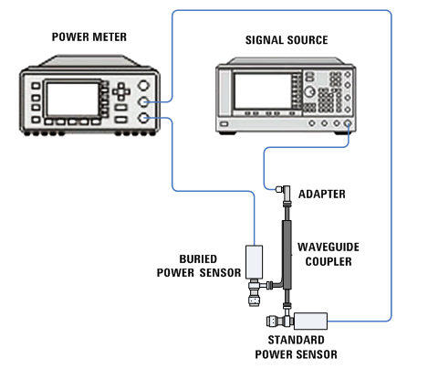
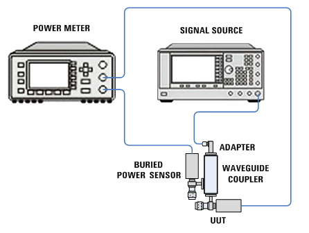
It is recommended to use a clamp to hold the directional coupler during the test.
The power sensor (UUT) calibration factor uncertainty is stated as an absolute uncertainty. Stating calibration factor uncertainty as an absolute uncertainty allows for a consistent reporting format in TME.
Calibration factor uncertainty can be stated as a relative or an absolute number. Traditionally, calibration factor uncertainty has been stated as a relative number. Measurement uncertainty calculations require that this parameter be a relative term. It is critical that this distinction between absolute and relative uncertainties be understood when performing measurement uncertainty calculations. The power sensor (UUT) relative calibration factor uncertainty can be derived from the absolute calibration factor uncertainty by the following equation:
Relative calibration factor uncertainty = 100% × (Absolute calibration factor uncertainty) / (Calibration factor)
In general, the difference between the relative and absolute uncertainty is less than 10%. This small difference is because calibration factor values tend to be greater than 90% on a typical power sensor.
The cal factor uncertainty of the Standard Power Sensor is the most significant contributor to the overall measurement uncertainty of the calibration factor test. Other factors, such as the mismatch and the repeatability of the test system are significant; however, choosing an appropriate reference power sensor is critical to the reported calibration factor uncertainty.
TME recommends using a Standard Power Sensor with Option H84. H84 sensors are calibrated at the required cardinal frequencies using the Standards Lab calibration service. This provides the lowest possible uncertainty.
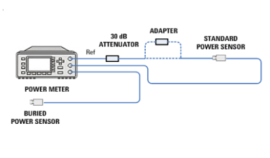
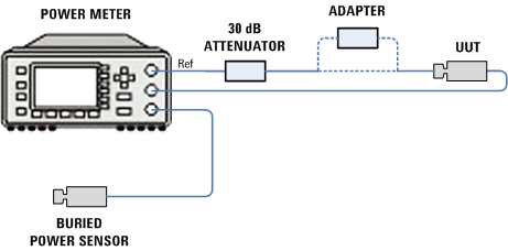
The calibration factor uncertainty of the 8485D UUT depends on the calibration factor uncertainty of the 8485D Standard Power Sensor. The calibration factor uncertainty of the Standard Power Sensor is smaller when calibrated by itself than when calibrated with the 11708A 30dB reference attenuator. To meet the Maximum Calibration Factor Uncertainty Specification of the UUT, it is recommended to have the Standard Power Sensor calibrated by itself without the reference attenuator. Ask your service provider to calibrate the 8485D Standard Power Sensor and reference attenuator separately.
|
|
To view the table below in its entirety, you may need to select the Hide Navigation button from the toolbar. |
| Instrument | Recommended product | Alternative product | N8481A (all except Opt 200), 8481A | N8481A Opt 200 | N8482A, 8482A | N8485A (all except Opt 033), 8485A, 8485D | N8485A Opt 033 | N8487A, 8487A | N8488A | E9304A | E9304A Opt H18 | N8486AR, N8486AQ |
N8481H, N8481B | N8482H, N8482B |
| Signal Generators | ||||||||||||||
| Signal Generator | E8257D Opt 1E1, (1EA or 1EU), and (550 or 567)[1] |
- | X | X | X | X | X | X | X Opt 1E1, (1EA or 1EU), and 567 |
X | X | X | X | X |
| Function Generator | 33622A |
33612A |
X | X | X | X | ||||||||
| Power Supply | 87422A | - | X | X | ||||||||||
| Meters | ||||||||||||||
| Power Meter | N1914B |
N1914A E4419B N1912A |
X | X | X | X | X | X | X | X | X | X | X | X |
| Power Sensor (3 required)[2][8] |
N8481A | 8481A | X | |||||||||||
| Power Sensor (3 required)[2] |
N8481A Opt 200 | 8481A Opt 001 | X | |||||||||||
| Power Sensor (3 required)[2][8] |
N8482A | 8482A For UUT N8482A Frequency range: 100 kHz to 50 MHz For UUT 8482A Frequency range: 100kHz to 4.2 GHz |
X For UUT N8482A, 8481A (Frequency range: 50 MHz to 6 GHz) is used with the 8482A as an alternative product. |
|||||||||||
| Power Sensor (3 required)[2][8] |
N8485A | 8485A | X For UUT N8485A and 8485A only |
|||||||||||
| Power Sensor (3 required)[2] |
N8485A Opt 033 | 8485A Opt 033 | X | |||||||||||
| Power Sensor (3 required)[2] |
8485D | - | X For UUT 8485D only |
|||||||||||
| Power Sensor (3 required)[2][8] |
N8487A | 8487A | X | |||||||||||
| Power Sensor (3 required)[2][8] |
N8488A | - | X | |||||||||||
| Power Sensor (3 required)[2] |
E9304A | - | X | |||||||||||
| Power Sensor (3 required)[2] |
E9304A Opt H18 | - | X | |||||||||||
| Power Sensor (3 required)[2] |
N8486AR |
R8486A |
X For UUT N8486AR only |
|||||||||||
| Power Sensor (3 required)[2] |
N8486AQ |
Q8486A |
X For UUT N8486AQ only |
|||||||||||
| Power Sensor (3 required)[2][8] |
N8481H |
8481H |
X | |||||||||||
| Power Sensor (3 required)[2][8] |
N8482H | 8482H (Frequency range: 100 kHz to 50 MHz) and 8481H (Frequency range: 50 MHz to 6 GHz) |
X | |||||||||||
| Power Splitters[8] | ||||||||||||||
| Splitter | 11667A | - | X | X | X | X | X | X | ||||||
| Splitter | 11667A Opt 002 | - | X | |||||||||||
| Splitter | 11667B | - | X | X | ||||||||||
| Splitter | 11667C | - | X | |||||||||||
| Splitter | 11667CH65 Opt H70 |
- | X | |||||||||||
| Directional Couplers | ||||||||||||||
| WG22 Multihole Directional Coupler | Flann Microwave 22132-10 |
- | X For UUT N8486AR only |
|||||||||||
| WG23 Multihole Directional Coupler | Flann Microwave 23136-10 | - | X For UUT N8486AQ only |
|||||||||||
| Power Amplifiers | ||||||||||||||
| Low Frequency Power Amplifier |
R&K Company Limited A3000-2H-R |
- | X | X | ||||||||||
| High Frequency Power Amplifier | 83020A | - | X | X | ||||||||||
| Attenuators | ||||||||||||||
| 30 dB Attenuator | 11708A | - | X For UUT 8485D only |
|||||||||||
| 10 dB Attenuator | 8491B Opt 010 | - | X Alternative product: 8491A Opt 010 |
X | ||||||||||
| Adapters | ||||||||||||||
| Type-N (m) to 2.4 mm (f) |
11903D |
- | X | X | X | X | X | |||||||
| Type-N (m) to BNC (m) |
1250-1473 | - | X | X | X | X | X | |||||||
| 2.4 mm (f) to 3.5 mm (m) |
11901D | - | X | X | ||||||||||
| 2.4 mm (f) to 3.5 mm (f) |
11901B |
- | X | X | ||||||||||
| 3.5mm (f) to Type-N (m) | 1250-1744 |
- | X | X | ||||||||||
| 3.5 mm (f) to Type-N (m) | 08485-60005 | - | X | X | ||||||||||
| 2.4 mm (f) to Type-N (m) | 08487-60001 | - | X | X | ||||||||||
| APC-7 to Type-N (m) | 85054-60032 | 11525A | X | |||||||||||
| WR-28 to 2.4 mm (m) |
R281B |
R281A WR-28 to 2.4 mm (f) |
X For UUT N8486AR only |
|||||||||||
| WR-22 to 2.4 mm (m) | Q281B | Q281A WR-22 to 2.4 mm (f) |
X For UUT N8486AQ only |
|||||||||||
| Cables | ||||||||||||||
| 2.4mm (f) to 2.4mm (f) |
Huber and Suhner Sucoflex 101_PE |
8120-6164 2.4 mm (m) to 2.4 mm (f) (Used with Q/R281A) |
X | |||||||||||
| 3.5mm (m) to 3.5mm (m) |
11500E |
- | X | X | ||||||||||
| 3.5mm(m) to 3.5mm(m) (2 required) | 5062-6656 | - | X | X | ||||||||||
[1] Supported E8257D options: This calibration application software supports any Option that covers the entire frequency range of the UUT and the required power level.
| UUT Model | Critical Specifications | Recommended Model | |
| N8481H, N8481B, N8482H and N8482B
|
Frequency range: (refer to UUT frequency range)
Power level: –20 to –5 dBm |
E8257D Opt 520 or 521 or 532 or 540 or 550 or 567
|
|
| N8486AR
|
Frequency range: (refer to UUT frequency range)
Power level: –10 to +7.24 dBm |
E8257D Opt 540[4] or (1EA/1EU and 550)[6] or (1EA/1EU and 567)[6]
|
|
| N8486AQ | Frequency range: (refer to UUT frequency range)
Power level: –10 to +7.34 dBm |
E8257D Opt 1EA/1EU and (550 or 567)[6] | |
| N8481A, N8482A, 8481A and 8482A | Frequency range: (refer to UUT frequency range)
Power level: –10 to +7 dBm |
E8257D Opt 520[7] or 521 or 532 or 540 or (1EA/1EU and (550 or 567)) | |
| N8485A and 8485A | Frequency range: (refer to UUT frequency range)
Power level: –10 to +7 dBm |
E8257D Opt 532 or 540 or (1EA/1EU and (550 or 567)) | |
| 8485D | Frequency range: (refer to UUT frequency range)
Power level: –40 to -24 dBm |
E8257D Opt 1E1 and (532 or 540 or 550 or 567) | |
| N8487A and 8487A | Frequency range: (refer to UUT frequency range)
Power level: –10 to +3.5 dBm |
E8257D (Opt 550 or 567)[4][5] | |
| N8488A | Frequency range: (refer to UUT frequency range)
Power level: –10 to +3.5 dBm |
E8257D (Opt 567)[4][5] | |
| E9304A | Frequency range: (refer to UUT frequency range)
Power level: –15 to +7 dBm |
E8257D Opt 520 or 521 or 532 or 540 or (1EA/1EU and (550 or 567)) |
PSG Options:
| PSG Serial number prefix | PSG Option details | |
| [4] | SN prefix < 49280000 |
If there is option 1E1, 1EA/1EU must be present |
| [5] | SN prefix ≥ 49280000 |
If there is option 1E1, 1EU must be present |
| [6] | SN prefix < 49280000 |
If there is option 1E1, UNW & 1EH cannot be present |
| [7] | SN prefix < 49280000 | If there is 1E1 & 1EH, must have 1EA/1EU present |
[2] For each power sensor model, three units are required to be used as the test equipment below:
Supported power sensor options:
8485A: Standard Option or 033
[8] Refer to the Required Calibration Data section in the Test Equipment page for the calibration options that meet the TME requirement on the test equipment’s calibration data.

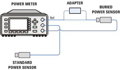
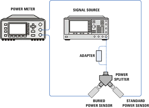
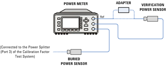
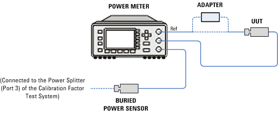
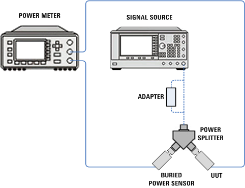
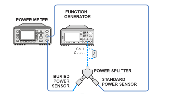
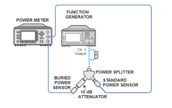
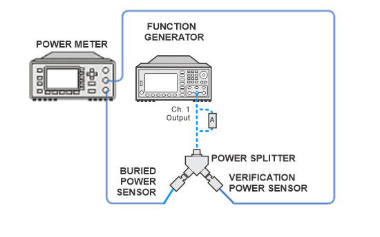
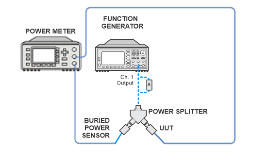
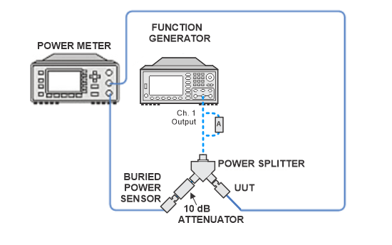
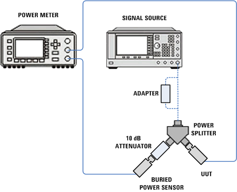
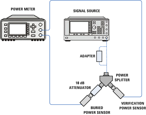
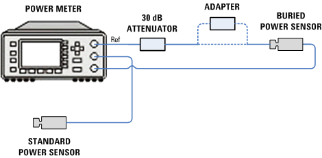
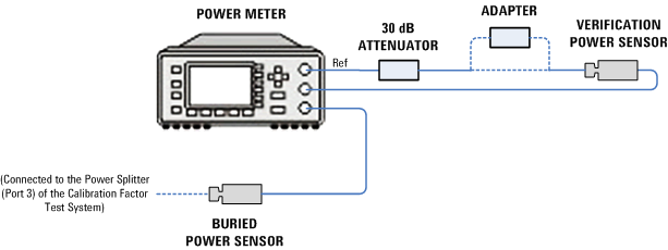
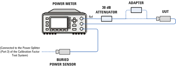
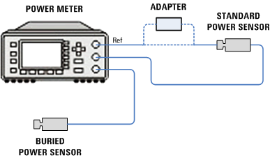
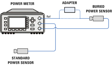
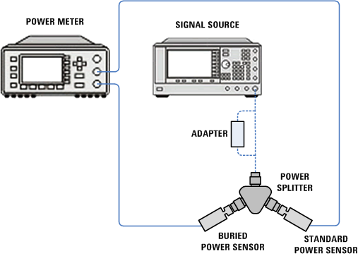
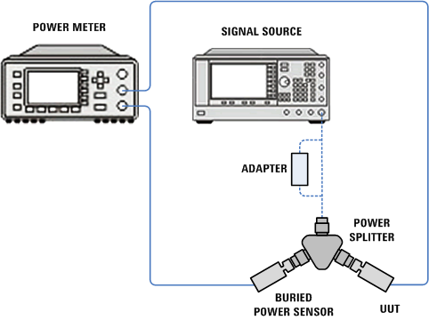
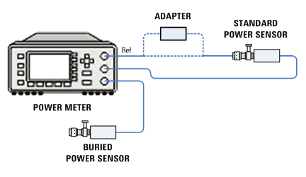
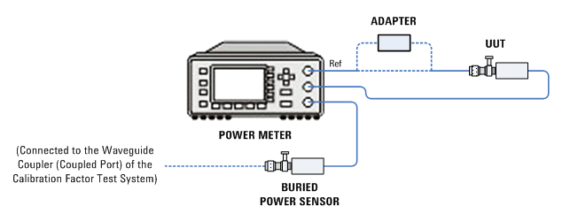
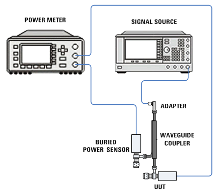
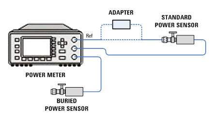
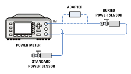
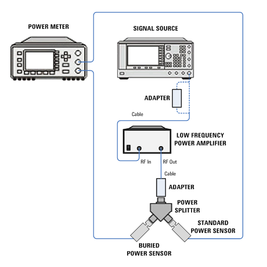
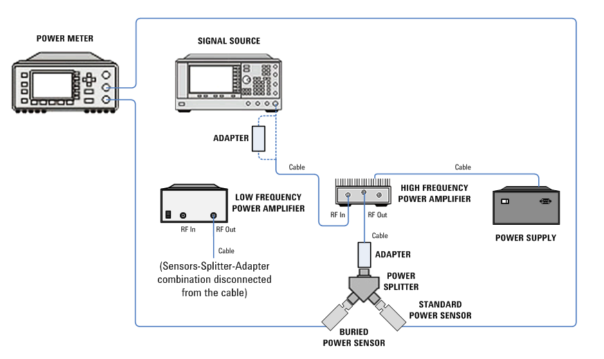
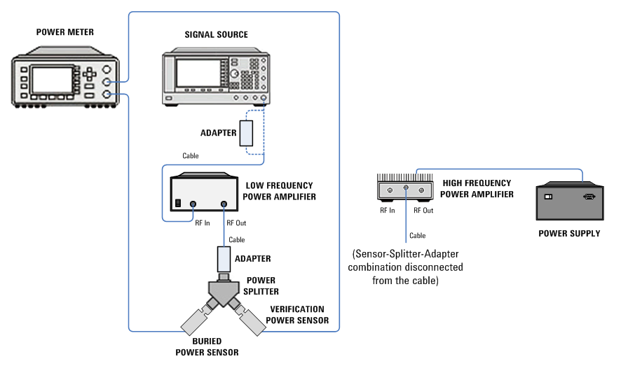
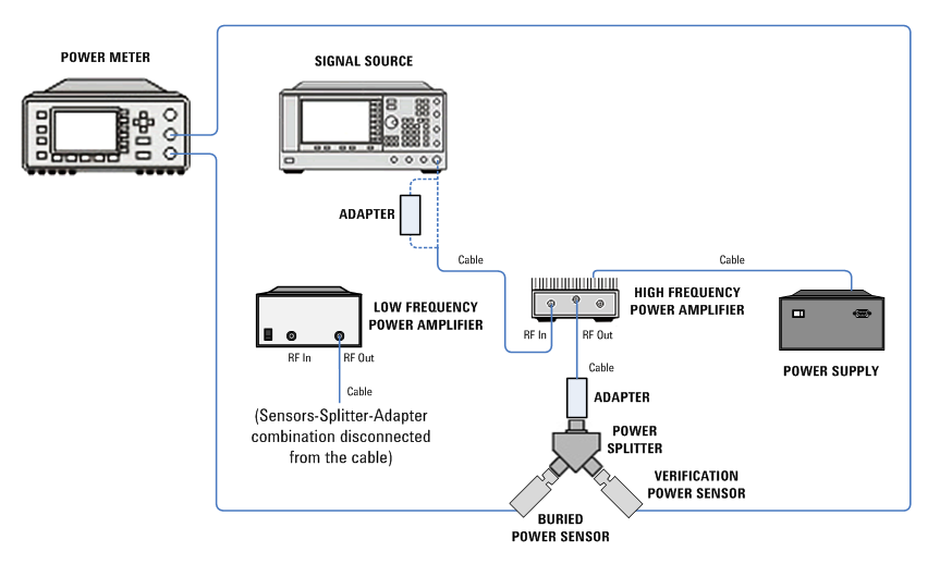
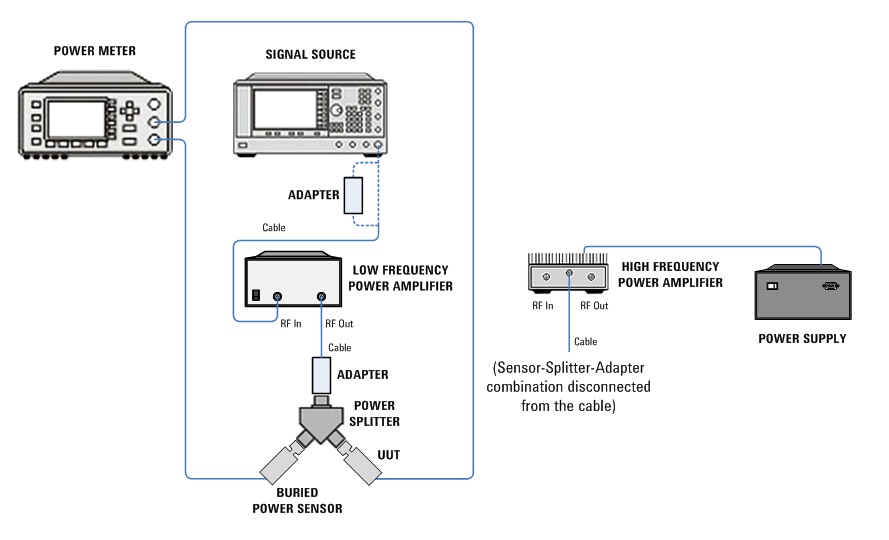
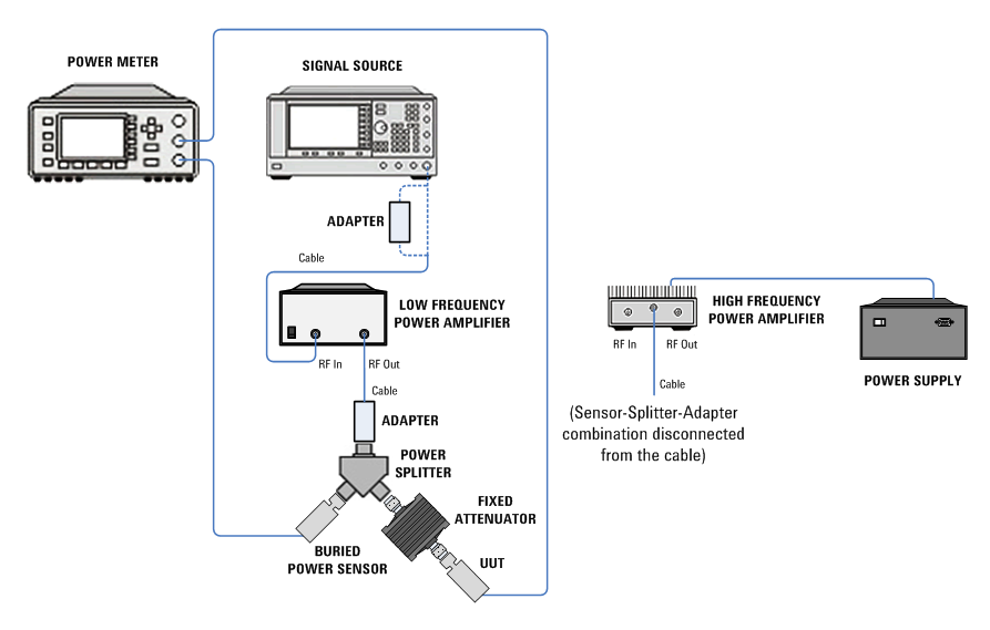
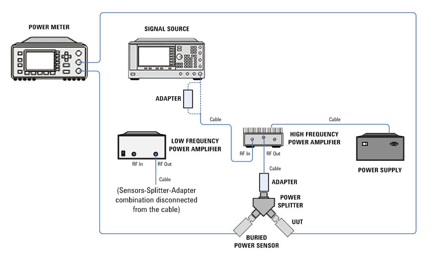
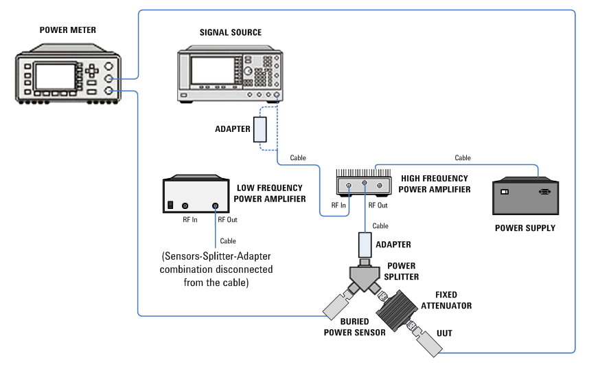
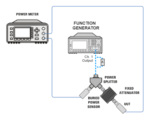
Select from the links below to view the setup images for your model number.


For UUT N8482A and 8482A:
For UUT E9304A and E9304A Opt H18
For UUT N8482A and 8482A:
For UUT E9304A and E9304A Opt H18:

For UUT N8482A and 8482A:
For UUT E9304A and E9304A Opt H18:
For UUT N8482A and 8482A:
For UUT E9304A and E9304A Opt H18:
For UUT N8482A and 8482A:
For UUT E9304A and E9304A Opt H18:
For UUT N8482A and 8482A:
For UUT E9304A and E9304A Opt H18:


For UUT N8481H:
For UUT N8481B:
For UUT N8481H:
For UUT N8481B:
For UUT N8482H:
For UUT N8482B:
For UUT N8481H:
For UUT N8481B:
For UUT N8482H:
For UUT N8482B:
