The VSWR test should be performed prior to running this test.
|
|
The VSWR test should be performed prior to running this test. |
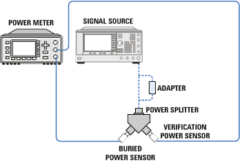
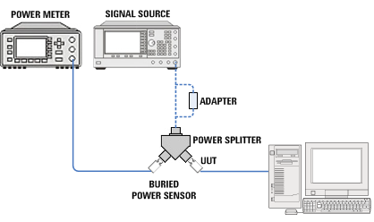
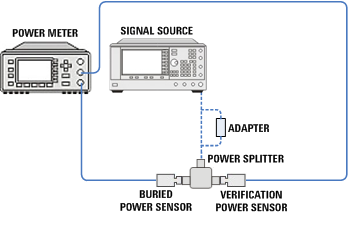
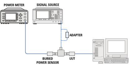
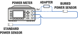
The purpose of this test is to characterize the calibration factor of the power sensor at each frequency parameter. The calibration factor created will be used as the correction for the power measured.
The power sensor (UUT) calibration factor uncertainty is stated as an absolute uncertainty. Stating calibration factor uncertainty as an absolute uncertainty allows for a consistent reporting format in TME.
Calibration factor uncertainty can be stated as a relative or an absolute number. Traditionally, calibration factor uncertainty has been stated as a relative number. Measurement uncertainty calculations require that this parameter be a relative term. It is critical that this distinction between absolute and relative uncertainties be understood when performing measurement uncertainty calculations. The power sensor (UUT) relative calibration factor uncertainty can be derived from the absolute calibration factor uncertainty by the following equation.
Relative calibration factor uncertainty = 100% × (Absolute calibration factor uncertainty) / (Calibration factor)
In general, the difference between the relative and absolute uncertainty is less than 10%. This small difference is because calibration factor values tend to be greater than 90% on a typical power sensor.
The cal factor uncertainty of the Standard Power Sensor is the most significant contributor to the overall measurement uncertainty of the calibration factor test. Other factors, such as the mismatch and the repeatability of the test system are significant; however, choosing an appropriate reference power sensor is critical to the reported calibration factor uncertainty.
TME recommends using a Standard Power Sensor with Option H84. H84 sensors are calibrated at the required cardinal frequencies using the Standards Lab calibration service. This provides the lowest possible uncertainty.
| Instrument | Recommended product | Alternative product | U2000A, U2001A | U2002A | U2004A | U2000B, U2001B | U2000H, U2001H | U2002H |
| Signal Generators | ||||||||
| Signal Generator | E8257D Opt (1EA or 1EU) and (532, 540, 550, or 567) |
- | X | X | X | X | X | X |
| Function Generator | 33622A | - | X | |||||
| Power Supply | 87422A | - | X | X | X | |||
| Meters | ||||||||
| Power Meter[1] | N1914A |
N1912A E4419B |
X | X | X | X | X | X |
| Power Sensor (3 required)[2, 3] |
N8481A | 8481A | X | X | X | |||
| Power Sensor (3 required)[2] |
E9304A | - | X | |||||
| Power Sensor (3 required)[2, 3] |
N8485A | 8485A | X | X | ||||
| Power Sensor (3 required)[2, 3] |
N8481H | 8481H | X | |||||
| Power Splitters | ||||||||
| Splitter[3] | 11667A | - | X | X | X | X | ||
| Splitter[3] | 11667B | - | X | X | ||||
| Attenuators | ||||||||
| Fixed Attenuator | 8491A Opt 020 |
8491B Opt 020 | X | |||||
| Fixed Attenuator | 8491B Opt 010 |
- | X (Alt: 8491A Opt 010 for U2001H) |
|||||
| Fixed Attenuator | 8493C Opt 010 |
- | X | |||||
| Fixed Attenuator | 8491B Opt 003 | - | X (Alt: 8491A Opt 003) |
X | ||||
| Adapters | ||||||||
| Type-N (m) to 2.4 mm (f) |
11903D |
- | X | X | X | X | ||
| Type-N (m) to BNC (m) |
1250-1473 | - | X | |||||
| 2.4 mm (f) to 3.5 mm (m) |
11901D | - | X | X | ||||
| 3.5 mm (f) to Type-N (m) | 08485-60005 |
- | X | X | ||||
| Amplifiers | ||||||||
| Amplifier |
R&K Company Limited A3000-2H-R |
- | X | X | X | |||
| Amplifier | 83020A | - | X | X | X | |||
|

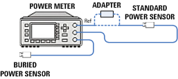
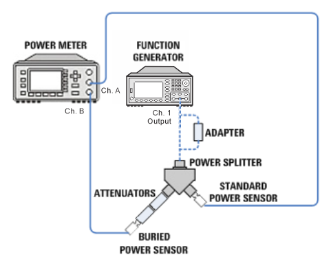
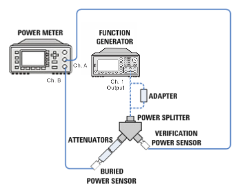
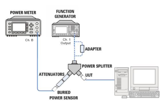
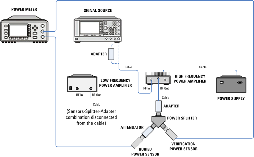
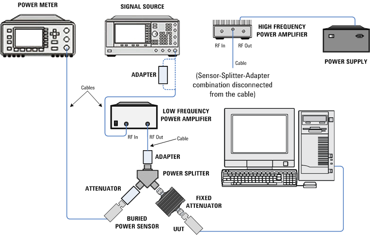
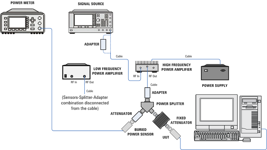
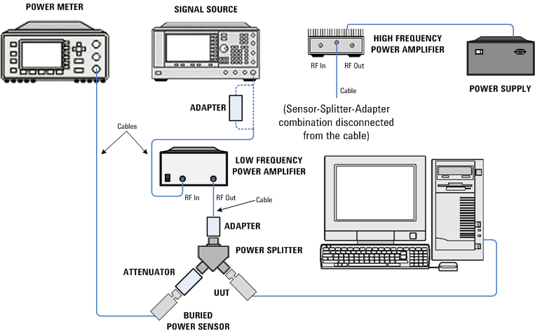
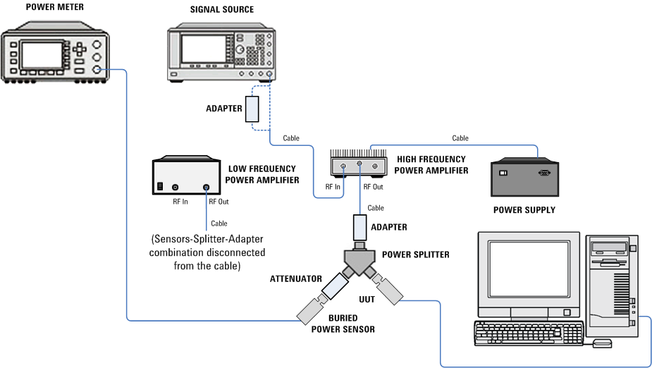
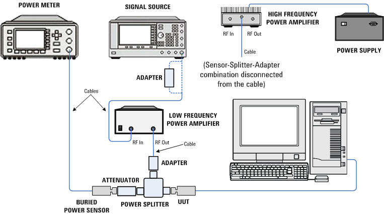
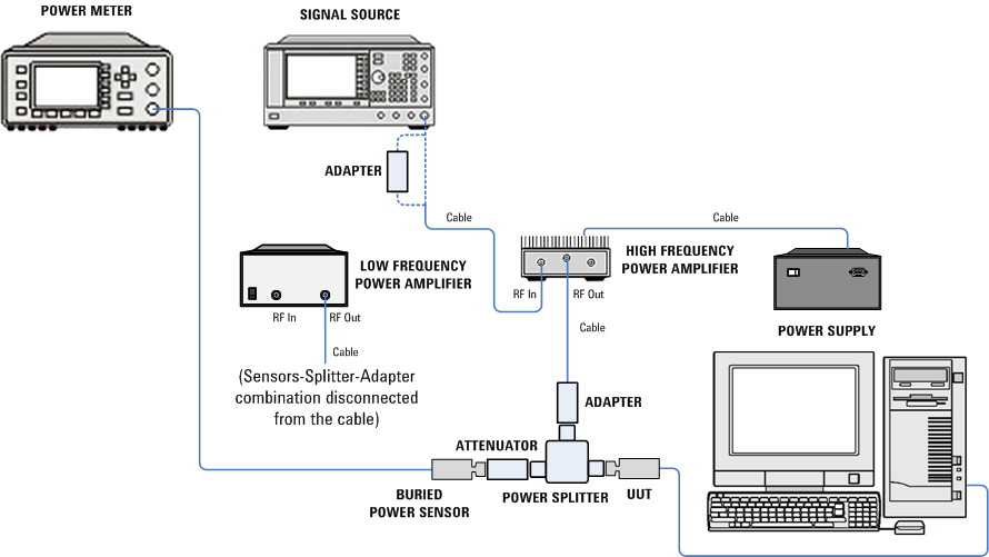
Select the link below for your power sensor model to go to the test setup illustrations for your model. To expand all, click the Expand All button  in the toolbar (webhelp only).
 U2000A and U2001A