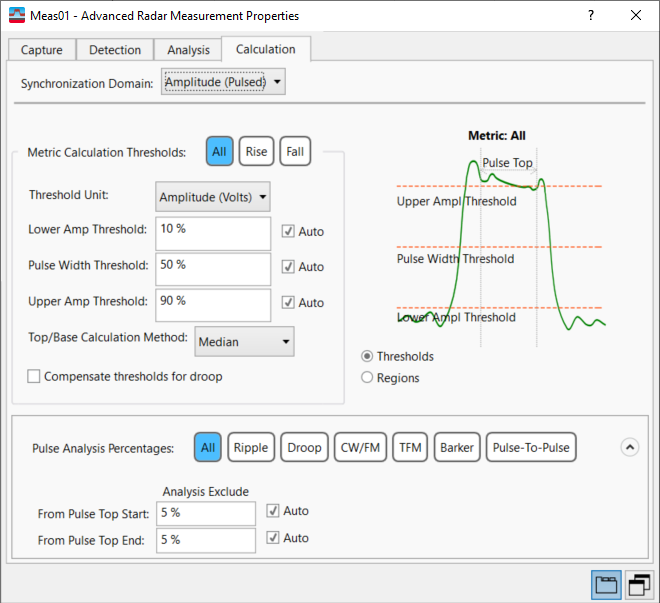
Calculation Tab (Advanced-Radar/Hopping)
Menu Path:
The Calculation tab provides inputs to configure how pulse and region metrics are calculated.

Synchronization Domain -- This parameter is provided on every tab because it is a fundamental configuration parameter affecting the entire Advanced-Radar/Hopping measurement.
____________________________________________
Metric Calculation Thresholds
The diagram on the right side of the Calculations tab will update dynamically for ease of understanding. The threshold settings are shown in the diagram when the Thresholds radio button is selected.
- Threshold Unit -- Specifies the units used during Pulse Rise/Fall Time threshold level calculations as either Amplitude (Volts) or Power (Volts2). Directly affects reported Rise Time, Fall Time, and Pulse Width Time analysis result metrics. Also affects reported units of Droop (%), Overshoot (%) and Ripple (%) result metrics.
Amplitude (Volts) -- All specified percentage threshold calculations are made using units of Volts.
Power (Volts2) -- All specified percentage threshold calculations are made using units of Volts squared.
-
Lower Amp Threshold -- Adjusts the lower amplitude threshold, which is used with the Upper Amp Threshold to calculate Rise Time and Fall Time.
-
Pulse Width Threshold -- Adjusts the amplitude threshold for calculating pulse width. The units are percent (%). Threshold is specified as percent of pulse top 100% amplitude or power level, depending on the specified Threshold Unit.
-
Upper Amp Threshold -- Adjusts the upper amplitude threshold, which is used with Lower Amp Threshold to calculate Rise Time and Fall Time.
-
Top/Base Calculation Method -- Determines how the Top Level and Base Level metrics are calculated for each detected pulse. Valid choices are “Mode”, “Median” or “Mean”. Measurements are based on IEEE Institute of Electrical and Electronics Engineers. A US-based membership organisation that includes engineers, scientists, and students in electronics and related fields. The IEEE developed the 802 series wired and wireless LAN standards. Visit the IEEE at http://www.ieee.org Std 181-2011, where a bi-modal histogram is generated for each individual detected pulse. The bi-modal histogram is then split into two sub-histograms representing pulse amplitude ON (Top) and Off (Base) regions. Top and Base Levels are derived as either the Mode, Median or Mean levels from each of the respective pulse amplitude sub-histograms. See the Pulse Measurement's Top/Base Calculation Method topic for more information.
If the noise floor of your signal is particularly high, this could interfere with the calculation of the Top/Base of the pulse, and thus interfere with the detection of the pulse. Consider using a Top/Base Calculation Method of Mean to compensate for this.
-
Compensate thresholds for droop
-
When checked (TRUE), the measurement compensates the Rise Time and Fall Time 100% Top Levels for Droop when applying Rise/Fall Thresholds. Note that the measurement uses the reported Droop Start (dBm deciBels referenced to a milliWatt: dB relative to 1 milliwatt dissipated in the nominal input impedance of the analyzer) and Droop Stop (dBm) levels as the Rise Time and Fall Time 100% Top Levels, respectively.
-
When unchecked (FALSE), the measurement does not compensate the Rise Time and Fall Time 100% Top Levels for Droop when applying Rise/Fall Thresholds. Note that the measurement uses the reported Top Level (dBm) as the Rise Time and Fall Time 100% Top Levels.
Pulse Analysis Percentages
The settings in this parameter group allow you to specify the portion of the pulse to do measurement metric computation for specific metrics and modulation types. Select a desired metric/modulation type (or select All) and set the From Pulse Top Start and From Pulse Top End "Analysis Exclude" parameters to define the portion of the pulse to be used in the calculation of that metric/modulation type. When the Regions radio button under the diagram is selected, these settings are shown in the diagram and the selected metric/modulation type is displayed after "Metric:" in the diagram's title.
-
From Pulse Top Start -- Specifies a percentage of the pulse top, from the start of the pulse top, to exclude from analysis. This defines the beginning of the portion of the pulse to be analyzed.
-
From Pulse Top End -- Specifies a percentage of the pulse top, from the end of the pulse top, to exclude from analysis. This defines the end of the portion of the pulse to be analyzed.
Region Analysis Percentages
(not available with Amplitude Synchronization Domain)
The settings in this parameter group allow you to specify the portion of the detected region for analysis. Frequency, phase, and chirp metrics within the Region Table are all affected by these parameters, as they affect the portion of the region to use for calculation.
-
From Region Start -- Specifies the percentage offset, from the start of the region, at which analysis begins. The Region Analysis Percentages parameters specify the portion of the region which is used for metric calculations such as Chirp Mean.
-
From Region End -- Specifies the percentage offset, from the end of the region, at which analysis ends. The Region Analysis Percentages parameters specify the portion of the region which is used for metric calculations such as Chirp Mean.
See Also
Advanced-Radar/Hopping Measurement Properties Dialog Box
