Doppler Tab (Advanced-Radar/Hopping)
Menu Path:
Range Doppler enables you to use received pulses to create a Range Doppler (Velocity) Map and identify targets present in the Doppler Map. Pulses/responses must be transmitted periodically, and you must know the period at which the pulses are transmitted. You can use either Non-Segmented Capture mode or Fixed Length Segmented Capture mode.
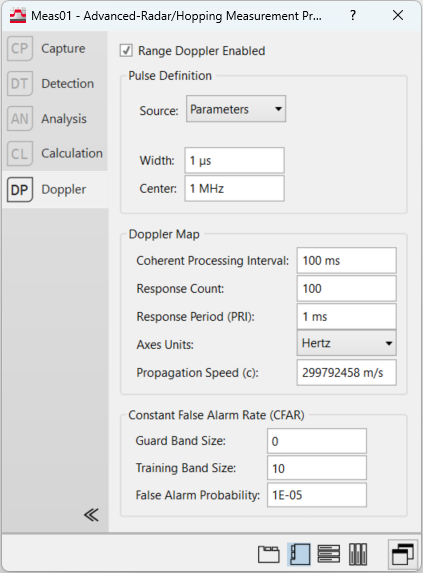
Range Doppler Enabled -- Enables and disables Range Doppler Analysis.
Pulse Definition
The first step to Range Doppler is doing a matched filter on the received pulses. This matched filter convolves the input signal with the transmitted pulse which must be specified by the user.
-
Source -- There are two methods of defining the pulse, indicated by setting the Source parameter.
-
Parameters -- The pulse used in the matched filter is generated using Width and Center parameters and passed through a Root-Raised Cosine filter.
-
Register -- The pulse used in the matched filter is taken from a register. The user can add their pulse to a register by using Recall Trace. This pulse should be at the same sample rate as the input signal.
-
-
Width -- (Source = Parameters) Specifies the width of the transmitted pulse in seconds.
-
Center -- (Source = Parameters) Specifies the frequency of the transmitted pulse in Hertz.
-
Data Register -- (Source = Register) Specifies the register that contains the expected pulse.
Doppler Map
The Doppler Map properties section specifies the parameters relating to the creation of the Range Doppler Map.
-
Coherent Processing Interval -- Specifies the interval over which all the pulses are received. CPI = Response Count * Response Period. Changing this property will also change the Response Count and snap to the nearest valid value based on the already defined Response Period.
-
Response Count -- Indicates the number of responses required to generate the Range Doppler Map. Changing this property will also change the CPI.
-
Response Period -- Indicates the expected time between acquisitions. If the acquired responses do not match this period, the traces will appear as empty, as they need to be evenly spaced to create an accurate Doppler Map. Changing this property will also change the Coherent Processing Interval.
-
Axes Units -- Axes Units has two options that determines the units on the Range Doppler Map.
-
Hertz -- Sets the units on the X-axis to seconds and the units on the Y-axis to Hertz
-
m/s -- Sets the units on the X-axis to meters and the units on the Y-axis to meters/second.
-
Constant False Alarm Rate (CFAR)
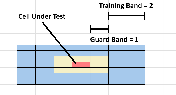
Constant False Alarm Rate (CFAR) is a method used to find targets in a Range Doppler Map. In CFAR,each sample is tested individually (called the Cell Under Test) and compared to surrounding samples (called Training Cells). If the power of the Cell Under Test is greater than the Threshold, that cell is identified as part of a target. The Threshold is calculated by:

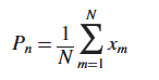
The Noise Estimate (Pn) is calculated by averaging the power in all of the training cells, where N is the number of training cells:
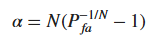
The alpha value is calculated by using the False Alarm Probability and the number of samples in the training band N:
-
Guard Band Size -- Specifies the number of samples on each side of the sample we are testing to see if it is part of a target. CFAR calculates a noise estimate from these training samples and compares it to the test sample to determine whether the test sample is a target.
-
Training Band Size -- Specifies the number of samples on each side of the sample to exclude from training.
-
False Alarm Probability -- Used alongside the noise estimate to determine the threshold which a test sample should be over to be considered a target.
See Also
Advanced-Radar/Hopping Measurement Properties Dialog Box