Digital Demodulator Block Diagram
The following block diagram shows the digital demodulator used for all demodulation formats except FSK, CPM (FM), and Shaped QPSK. To see how the Digital Demodulator fits into the overall instrument block diagram, see Digital Demodulation Block Diagram.
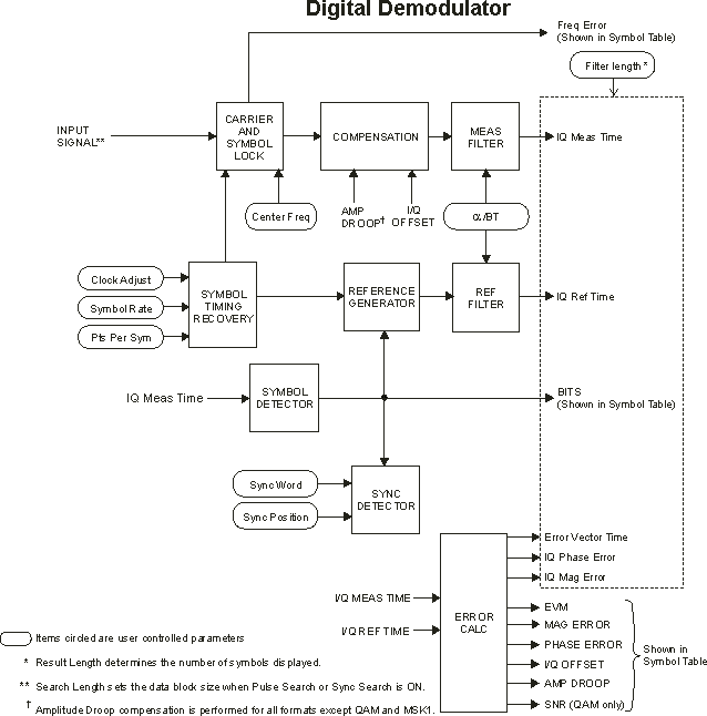
For systems that use Raised Cosine (also known as Nyquist) matched filtering, use Raised Cosine filtering for the reference filter and Root Raised Cosine filtering for the measurement filter. For MSK Minimum Shift Keying, the measured filter is applied before carrier lock.