Digital Demodulation Block Diagram
The following block diagram shows how the 89600 VSA performs digital, demodulated measurements. This block diagram applies to all demodulation formats. For a detailed block diagram of the digital demodulator (the block labeled Digital Demodulator, see Digital Demodulator Block Diagram).
If the the measurement hardware has two input channels, it is possible to remove the quadrature mixer from the following block diagram. This allows connection of the I (In-phase) signal directly to Channel 1 and the Q (Quadrature-phase) signal directly to Channel 2. For details, see Connecting Your Signal to the VSA.
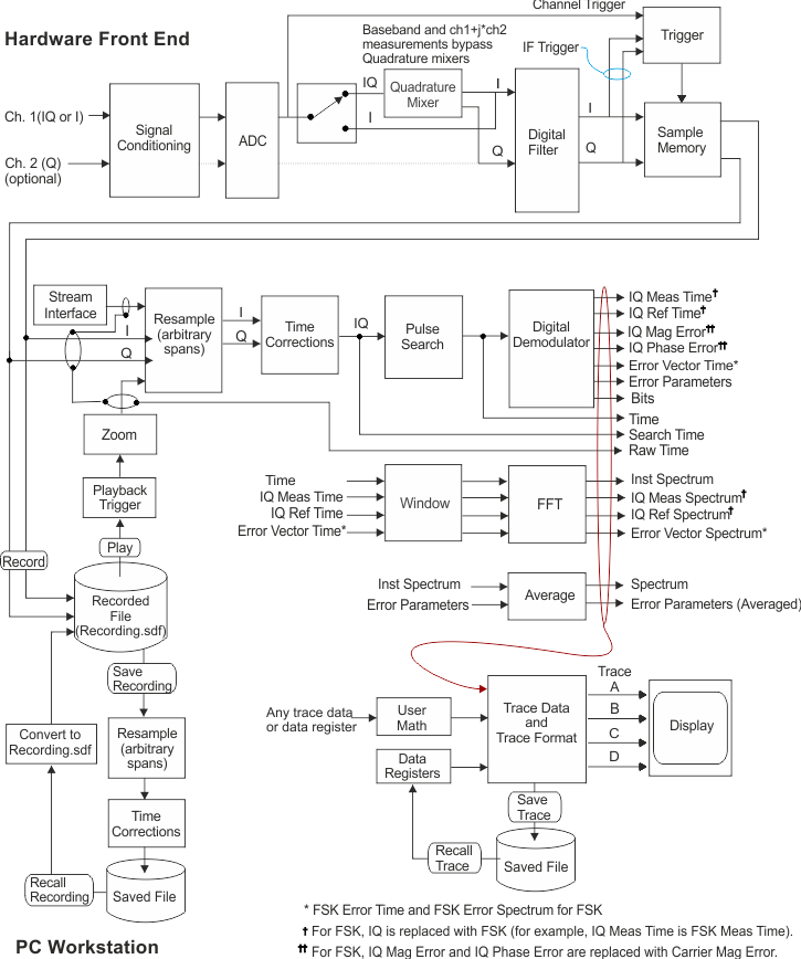
As shown in the block diagram, the VSA uses the demodulated signal to generate an ideal reference signal. The reference signal is the signal that would result after demodulating your signal if your signal were ideal (contained no errors). Compare the measured signal to the reference signal to quantify and locate errors in your signal.