Error Vector Time (GSM/EDGE/EDGE Evolution)
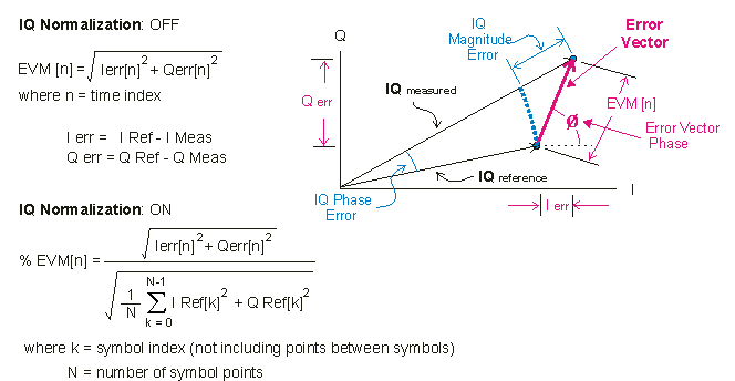
shows the error vector trace data results for each symbol. This trace displays the error vector for corresponding symbol points in the measured I/Q and reference I/Q signals. The error vector is the difference between the measured and reference symbol points.
The magnitude, phase, the real component, or imaginary component of the error vector can be viewed.
Trace Data Formats
The trace is a time record made up of complex, time-domain data. Each point in the time record has two components: I and Q. To make sense of the data, select an appropriate trace data format ( drop- down list).
- Linear Mag : Displays the EVM Error vector magnitude (EVM): A quality metric in digital communication systems. See the EVM metric in the Error Summary Table topic in each demodulator for more information on how EVM is calculated for that modulation format. (Error Vector Magnitude).
- Real(I) : Displays the I component of the error vector.
- Imag(Q) : Displays the Q component of the error vector.
- Wrap Phase: Displays the Error Vector phase error.
For example, to see the error-vector magnitude, select the Linear Mag trace format (). Selecting shows the square root of the sum of the squares for each complex pair of points in the time record, which is the error-vector magnitude (EVM).
When Normalize IQ Traces is cleared, the trace shows the instantaneous error-vector magnitude for each point. When is selected, the trace shows the error vector magnitude as a percentage of the RMS average of the ideal signal for the Timeslot. This is shown in the graphic below.

When the error vector results in this trace are different than expected, see the troubleshooting tips in Troubleshooting.
compares all points in the measured IQ signal and reference IQ signal. For all modulation schemes, there is only one point per symbol, except for GMSK Gaussian Minimum Shift Keying, where there are 10 points per symbol.
When using band-power markers, all the points on the trace within band-power markers are included in band-power calculations, unlike the Summary Table data results which only use the symbol decision points for calculating error summary information.
View the measured IQ signal in the IQ Meas Time trace and the reference IQ signal in the IQ Ref Time trace.
See Also
