Frequency Mask Trigger Editor (Trigger)
The is used to create and manage frequency masks to be used with the Frequency Mask trigger style.
The Editor divided into two sections. The left side of the dialog contains a set of Mask Definition controls used to create, modify, and delete masks. The right side of the dialog shows the FMT trace window with a spectrum trace, overlayed with the upper and lower frequency masks.
You can modify the masks in either section of the editor. On the left, you can edit the numerical coordinates of the points that define the mask; and on the right, you can modify the mask geometry by clicking and dragging the mask points. There is also a toolbar with measurement control and trace buttons as well as a control to change the mask color.
- FMT Measurement
- Trigger Measurement Settings
- Trace Mode
- Mask Color and Opacity
- Frequency and Amplitude Mask Offsets
- Active Masks
- Creating a Mask
- Trace Selection
- Modifying a Mask
- Importing and Exporting Masks
FMT Measurement
When the FMT Editor opens, the VSA creates a new measurement that emulates as closely as possible the measurement that will be performed by the FMT trigger hardware. Note that the measurement used by the mask editor is not real-time or gap-free and is an untriggered (FreeRun) measurement. The intent is to allow you to see the spectrum of your signal so that you can build a mask that will capture the desired trigger event.
When a true real-time measurement is needed when creating the mask, you can use the Real Time Spectrum Analyzer (RTSA) user interface to create and save a mask, and then import the RTSA mask into the VSA.
You can control the FMT measurement through the Control toolbar above the trace window, which contains buttons to restart, pause or continue the measurement, and to determine whether the sweep mode is Single or Continuous. See the VSA's Control Toolbar topic for more information.

Restarting the measurement will clear the Cumulative History display.
Trigger Measurement Settings
The FMT control parameters in the tab are duplicated in the FMT Editor in the group box. Here you can adjust the window type and resolution bandwidth used by the FMT hardware when searching for a trigger event. Note that changing these parameters will also affect the VSA's FMT measurement as well. This is so that you can preview the effect of changing these parameters while building your mask.
For more information about these parameters, see the Frequency Mask trigger style.
Trace Mode
By default, the FMT editor's spectrum trace is configured to use the Cumulative History trace mapping. You can use the Trace toolbar to toggle between Cumulative History and a regular Spectrum trace and to adjust the threshold for the cumulative history display (for a tighter mask when using the button).

Mask Color and Opacity
It may be difficult to view the masks depending on the cumulative history and trace colors. The mask color selector in the toolbar allows you to control both the color and the opacity of masks.

This color/opacity setting does not affect masks shown on other traces in the VSA.
The color is specified in amounts of Red, Green, and Blue. The contribution of a primary color is from 0 (none) to 255. Opacity can be changed from 0% (completely transparent) to 100%.
To alter any of the four values, click on the value to select it. Then use the keyboard arrow keys to increment or decrement the value, or use the mouse on the arrow buttons at the right.
You can click the drop-down button on the far right of the color selector to open a panel that allows more advanced control over the color.
Frequency and Amplitude Mask Offsets
The offset and offset parameters are used to shift the in either frequency or amplitude. The offsets apply to the entire mask.
Both the Upper and Lower masks have their own offset parameters.
You can also adjust the frequency and amplitude offsets while a measurement is running by using the corresponding offset parameters on the tab.
Active Mask
The FMT editor trace window shows both upper and lower masks simultaneously, but you can only modify one at a time. You can choose which mask to edit by selecting Upper or Lower in the group box. Clicking on a mask in the trace window will also set that mask as the active mask.
Creating a Mask
There are three methods available to create a new mask:
- : clicking the button creates a default mask consisting of 4 control points. The upper mask shape is a trapezoidal shape and the lower mask is an inverted representation of the upper mask.
-
: clicking the button builds a mask from the envelope of the data shown in the FMT trace window. Note that the envelope includes all historical data displayed by the cumulative history.
The cumulative history Threshold (in the toolbar) can be adjusted to eliminate less frequently occuring data so that clicking builds a "tighter" mask.
-
: The button builds a mask from an existing Limit Test.
To import a mask from a currently loaded VSA limit test, click the button. This opens the dialog box which contains a list of limit tests that each have one or more limit lines defined in the frequency domain. The dialog shows a preview of each mask with respect to the current measurement span. See the Importing and Exporting Masks section below for more information about the preview.
Trace Selection
The default trace source data is the spectrum from the VSA FMT measurement. The VSA also supports two additional spectral trace data sources: VSA spectrum trace data and data registers. You can select different trace data from the FMT trace tab drop-down list (Select the drop-down arrow on the FMT trace tab). The VSA supports the following trace data sources:
- Other traces containing Spectrum results
- Data registers containing amplitude vs. frequency data
This feature allows you to use previously captured spectral content to build your mask.
Modifying a Mask
The frequency mask editor supports the following operations:
There is always a selected control point. The selected point is indicated in the points table as a row with editable values, and in the trace window by a circle filled in red.


Every mask must have at least two control points.
You can change the selected point either by editing the selected row in the table, or by clicking on the control point on the trace. Once selected, you can move the control point either by changing the values in the table or by dragging the point in the trace window.
Adding/Inserting Control Points
To add a control point:
- Click the or button in the group box
- Right-click a mask control point and select or from the context menu
When you add a control point, it is added to the right of the selected control point. When you insert a control point, it is added to the left of the selected control point.
You can only add points to an existing mask. When there are no points in the selected mask, the and buttons will be disabled. To create the initial mask, use one of the methods described above.
Removing Control Points
To remove a control point:
- Click the button in the group box
- Right-click a mask control point and select from the context menu
When a mask has only two points, the button is disabled. You can delete all points in a mask by clicking the button in the group box.
Modifying Control Points
To modify a control point value in the table, click in the field you want to edit ("Frequency" or "Amplitude") and
- Type in a new value, or
- Increment or decrement the value using the arrow keys, or
- Increment or decrement the value using the mouse wheel
You can also modify the mask from the trace window by clicking a control point and dragging it to a new location. Moving the control point changes both the frequency and amplitude at the same time. However, you can constrain the change to be only frequency or amplitude, as follows:
- Hold down the "Ctrl" key while dragging to only change the amplitude, or
- Hold down the "Shift" key while dragging to change only the frequency
The cursor shape shows the allowed directions of movement.
Regardless of how you move a point, the frequency values allowed for a point are always constrained by the adjacent points. You cannot move a control point past the adjacent points in frequency.
You can also change multiple control points at the same time. To select multiple control points, hold down the "CTRL" key while clicking control points, either in the points table or in the trace window.
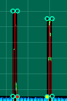
In the points table, the primary control point has the row with editable parameters and is shown in the trace window as the red-filled control point. Secondary control points are highlighted, but non-editable in the points table and are shown as a yellow-filled control point in the trace window.
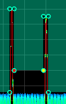
When multiple points are selected, any operation you perform on one is performed on all. The selected points all maintain their relative location to each other. This feature allows you to manipulate sections of the mask together. For example, note the primary and secondary points in the mask below (middle area):

You can move both points upwards by clicking and dragging one of the points, as shown in this screenshot.

Relative vs. Absolute
Both the amplitude and frequency control point coordinates can be specified as relative () or absolute () values.
When is selected for either type of coordinate, frequency coordinates are expressed relative to the measurement Center frequency and amplitude coordinates are expressed relative to the Range setting.
When switching between relative and absolute values, the coordinates of the control points in the upper and lower masks are adjusted so that the masks remain in the same absolute positions.
Importing and Exporting Masks
The following mask definitions are supported for import:
- RTSA FMT definition files (.csv)
- VSA Limit Line (.lim) or Limit Test files (.lims)
- VSA Limit Tests (currently loaded in the VSA)
You can also export a mask definition to an RTSA FMT definition file or create a VSA Limit Test from the mask definition.
Import/export differences:
- Relative amplitudes in RTSA FMT definition files are relative to the instrument's Reference Level, whereas in the VSA they are relative to the measurement's Range setting.
- The limit lines in a limit test can be relative to the trace , a specified , or a specific . See the Limit Line Y Reference parameter for more information.
It may be necessary to adjust the of the mask to adjust for these differences.
Importing a Mask from a file
Click the button in the FMT Editor to import masks from an RTSA FMT definition (.CSV), from a VSA Limit Test (.Lims), or Limit Line (.Lim) file.
When the dialog opens, follow the prompts to find and import the mask definition file.
Here are the default file locations. However, these file types can be stored anywhere on the file system.
- : My Documents\RTSA\data\FMT
- : My Documents\Keysight\89600B VSA\LimitTests
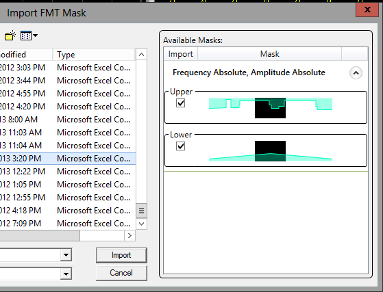
The dialog has a preview area that shows the approximate geometries of the mask(s) available in the file, and where they are located relative to the span of the current measurement. The black rectangle represents the measurement span/center. The cyan shading represents a mask in the file.
Importing from an RTSA definition file
Mask definition files created using the RTSA mode will have either an upper mask only, a lower mask only, both masks, or neither mask. Additionally, if both masks are present, they will both share the same absolute vs. relative attributes. You can choose to import either or both masks by selecting the appropriate check boxes and then clicking the button.
In the example below, the masks are clearly wider in span than the current measurement. Additionally, there is both an upper and a lower mask available in the file.

Importing from an 89600 VSA Limit line file (.lims)
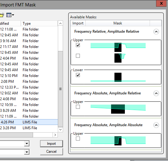
When you are importing from an 89600 VSA Limit Test file (.lims), there will be one or more masks present in the file. There can be multiple upper and multiple lower masks. The masks also need not share similar absolute vs. relative attributes. In such a file, the masks are grouped by their absolute vs. relative attributes.
In the file below there are a total of five masks available for import – four upper and one lower. You can import no more than one upper and one lower mask. Additionally, both the upper and the lower masks must share the same absolute vs. relative attributes. These rules are enforced as you make your selections.

You can also import a limit line as a mask from one of the currently loaded Limit Tests.
Exporting Masks to a File
You can export the current Upper and Lower masks to either an RTSA FMT definition file or to a Limit Test.
Exporting to an RTSA FMT Definition File
Click the button to export the masks defined in the FMT Editor to an RTSA-compatible file. The export function exports all defined masks regardless of which are actually in use by the FMT trigger. To simplify recalling into the RTSA application (when the VSA is running embedded in the instrument), save the file into the default folder (My Documents\RTSA\data\FMT).
Exporting to a VSA Limit Test
Select the button to create a VSA limit test from an FMT mask definition.
When the Limit Test Name dialog opens, specify the name of the limit test. By default, a unique name for a new limit test is provided. You can overwrite an existing limit test definition by providing its name.
See Also
