Measurement Channel (Input Analog Tab)
Menu Path:
parameter specifies the measurement channel(s) that the Analog input parameters will be applied. You can apply parameter settings to "ALL" Measurement channels or separately to each "individual" channel. The number of available Measurement channels is dictated by the measurement front-end input channel capability. The VSA will only enable valid analog input parameters for the current measurement front-end and Measurement channel configuration.
| : | The parameter applies the analog input parameter setting to all valid Measurement channels for the current measurement platform. |
| : | Use the Measurement Channel numbers to select and apply analog input parameters to individual Measurement channels. The analog parameter setting is only applied to the selected Measurement channel number. |
The selected Measurement channel is highlighted in green.
Switching Between the Number of Measurement Channels
When the selection is changed from an individual channel to "", the parameter settings for channel 1 are applied to the other active channels. When changing from "" to an individual channel, the parameter settings for all channels remain at their current (identical) values until otherwise set.
"Couple Paired Channels" property
The Couple Paired Channels property applies to the I+jQ Measurement channel type. Each I+jQ Measurement channel represents one IQ pair and is comprised of two measurement platform input channels, one I input channel and one Q input channel. When selected, the same analog input parameter setting is applied to both IQ pair input channels, When cleared, different analog parameter settings can be applied to each individual I and Q input channel.
Understanding VSA Measurement Channel
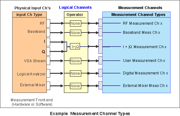
The VSA is defined by a channel mapping from the measurement front-end (hardware or software) inputs to the VSA measurement channel inputs. First the Physical Channel inputs are specified (this includes the input type and number of channels), next a Logical Channel Operator is specified, and finally the Logical Channel output is assigned to a Measurement Channel input. The type and number of available Physical Channel input types are determined by the measurement hardware (Baseband, RF Radio Frequency: A generic term for radio-based technologies, operating between the Low Frequency range (30k Hz) and the Extra High Frequency range (300 GHz)., I+jQ, Digital, User Input, etc.). Logical Channels and Operators is the mechanism used to modify and/or combine Physical Channels prior to being connected to the VSA Measurement Channel inputs. The VSA Measurement Channels are used for data analysis and trace data results.
The following graphic shows a few Measurement Channel mapping examples for various measurement front-end input types. Note that one "I+jQ" Measurement channel type requires two baseband input channels (one for the "I" input and one for the" "Q input).
Input Channel Type Presets
The input channel types available from the > "input channel types" menu are Presets that set the VSA to a default Measurement Channel mapping configuration. The available set of Input Channel presets are determined by the capabilities of the measurement front-end hardware. There is also a Custom Input Channel type that is used to create custom user-defined Measurement channel mapping configurations.
See Also