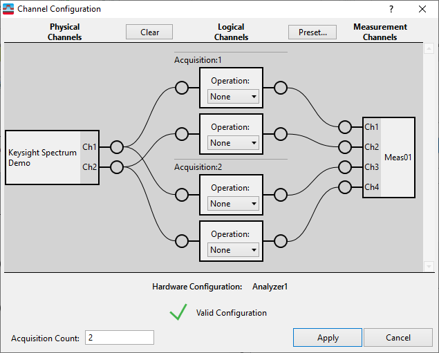
Channel Configuration Dialog (Input Channels)
Menu Path:
The Input menu item opens the dialog which allows you to manage custom measurement channel mapping configurations. In going from physical receiver hardware input ports to VSA measurement channels, you may use the Channel Configuration GUI to reconfigure the channel mapping. This dialogue is typically used to:
- Visually verify the current measurement channel mapping.
- Set up a non-standard custom measurement channels mapping.
- Configure Sequential Input Channel Acquisition measurements.
- Trigger on one channel but measure on other channels.
The dialog provides properties, operators, and a "drag and drop" GUI for ease of use.

Channel Configurations Parameters
| Item | Description |
|---|---|
|
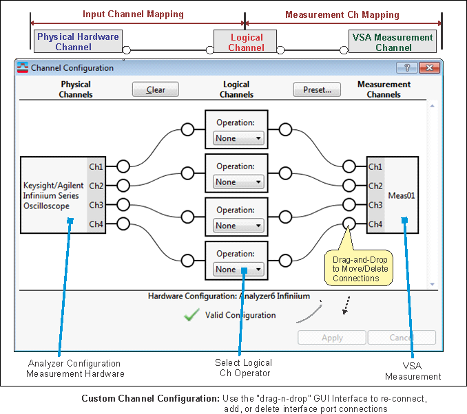
represent the input channels (or input ports) for each hardware front-end included in the measurement analyzer. For example, a four-port UXR oscilloscope would have 4 physical channels. The physical channel annotation includes the hardware logical instrument type and each input port is identified with a hardware number (only for multi-hardware analyzer configurations) and the input channel type (RF Radio Frequency: A generic term for radio-based technologies, operating between the Low Frequency range (30k Hz) and the Extra High Frequency range (300 GHz)., I, Q, Ch1, Ch2, etc). When you select one of the presets ( > select channel preset), the custom channel mapping will be overridden and reset to the input channel preset default channel mapping. |
|
|
provides a logical channel interface between the Physical Channel hardware "front-end" input ports and the measurement channel inputs. are used to:
When you select one of the presets ( > select channel preset), the custom channel mapping will be overridden and reset to the input channel preset default channel mapping. |
|
|
Measurements Channels are the VSA analysis measurement channels for the active measurement. For Shared multi-measurements, each measurement in the shared group is included in the GUI interface. The Measurement Channels interface annotation includes the VSA measurement name and channel number for each input channel. When you select one of the presets ( > select channel preset), the custom channel mapping will be overridden and reset to the input channel preset default channel mapping. |
|
|
Removes all physical-to-logical channel mapping connections. |
|
|
: Default re-sets the custom Logical Channel-to-Measurement Channel connections to the selected input channel preset mapping ( > selected input channel preset). For every connected logical channel ( logical channels that have a physical channel-to-logical channel input connection), each logical channel is connected to each measurement channel in descending order, i.e. logical channel 1 connects to measurement 01, logical Channel 2 connects to measurement 02 and so on. No intermediate channels can be skipped or bypassed. : 1 Channel/measurement (1 channel "per" measurement) re-sets the logical channel-to-measurement channel connections to a single channel measurement mapping (for multi-measurement configurations, each measurement is re-set to a single channel measurement mapping.). The logical channel-to-measurement channel mapping is connected in descending order. The first connected logical channel is connected to the first measurement, the second logical channel to the second measurement, and so on. All measurements must have a logical-to-measurement channel connection. When there are fewer connected logical channels than measurements channels, the first logical channel is re-used to satisfy the mapping requirement and make the additional measurement channel connection. : Removes all Logical Channels-to-Measurement Channels mapping connections. You can also use the Input Channels menu to reset the selected measurement to a preset measurement channel mapping. |
|
|
Configures up to 64 independent acquisitions for sequencing. |
|
|
Click to apply any Channel Configuration changes to the current measurement channel mapping. You must click the button to update the current measurement channel configuration, clicking the button will NOT update the current measurement. The APPLY button is disabled (greyed out) for invalid configurations. |
|
|
Cancel button options: : save and apply the channel mapping changes to the current measurement, close dialog. : do not apply the channel mapping changes, close the dialog. : Stop and exit the process, changes are not applied. Return to the Channel Configurations dialog. |
Status Indicators and Messages
The VSA auto-detects, in real time, valid and non-valid Channel Mapping connections and provides a status icon and corrective action message (Status/Message text is shown at the bottom of the Channel Configuration dialog):
- Check mark icon: Valid Channel Mapping connection.
- Check mark or icon: Indicates an invalid Channel Mapping with status message containing information about and/or action required to correct the invalid mapping. You will not be able to apply any changes until the channel mapping problem is fixed.
- Large icon covering any channel mapping links: Indicates any an invalid channel mapping connection.
Physical-to-Logical channel mapping:
Invalid Physical-to-Logical Channel mappings can be caused by one of the following conditions:
- Invalid Physical-to-Logical channel mappings is caused by attempting to make a hardware input port-to-logical connection that is not supported for the current measurement hardware.
- All Logical Channels must be connected in sequence from the first logical ch 1 thru the last used ch "n" (where Ch n is the last input channel), you cannot skip or bypass an intermediate logical channel. However, the physical channel inputs can be connected to the Logical channel inputs in any random order.
Logical-to-Measurement Channel mapping:
Invalid Logical-to-Measurement Channel mappings can be caused by one of the following conditions:
- All Measurement Channels must be connected in sequential order from the first measurement ch 1 thru the last used ch"n" (Ch 1, Ch 2, Ch 3,thru Ch n). Intermediate Measurement Channel inputs cannot be skipped or bypassed. However, the Logical channel outputs can be connected to the Measurement channel inputs in any random order.
- Connecting a Logical channel that does not have a Physical-to-Logical channel connection to a measurement channel is invalid.
- Connecting a Logical Channel to more than one Measurement channel is invalid.
How to Create a Custom Channel Mapping
The Channel Configuration dialog is used to create custom channel mappings. The Custom Configuration GUI shows the current measurement channel mapping connections and all non-connected available physical, logical, and measurement channel inputs for the selected "active" measurement configuration including:
- all available Physical Channel inputs for each hardware front-end in the measurement Analyzer Configuration,
- all available Logical Channels and Operators,
- all available measurement channel inputs for each measurement in a multi-measurement configuration.
Custom channel mappings are created by using the interactive "drag-n-drop" GUI interface to modify the Physical channel, Logical channel, and Measurement channel I/O port connections. The measurement channel mapping is divided into two channel mapping setups:
- Input Channel Mapping: Specifies the Physical-to-Logical channel connections.
- Measurement Channel Mapping: Specifies the Logical-to-Measurement channel connections.

Custom Channel Configuration procedure:
-
Configure the "Input Channel Mapping; make all the connections between the Physical Hardware Inputs to the Logical Channel inputs.
-
Specify each Logical Channel operator.
-
Configure the "Measurement Channel Mapping"; make all the connections between the Logical Channel outputs to the Measurement Channel inputs.
-
Click Apply button to update and save the new VSA channel mapping.
You must click the button to update the current measurement channel configuration, clicking the button will NOT update the current measurement.
Measurement Hardware Limitations:
Some Measurement hardware front ends have limited Custom Logical Channel functionality. To learn about specific Custom Channel functionality, see the Measurement Platform book and the "Custom Channel Configurations" measurement setup parameter description.
When you select one of the presets ( > select channel preset), the custom channel mapping will be overridden and reset to the input channel preset default channel mapping.
See Also
