Trig Out (Measurements tab)
In Synchronous Acquisition Mode, the property is used to align the time records acquired by independent measurements. Normally the order in which the measurements arm their respective hardware for triggering is undefined. Even when an external trigger is connected to all the hardware, one of the instruments could be armed and trigger before the other instruments, causing the time records to be unaligned (i.e. acquisition is Non-Synchronous).
aligns the time records by first arming all secondary hardware and then arming the primary hardware. Then when the primary instrument triggers, the trigger OUT signal from the primary instrument (which should be connected to all secondary instruments) triggers the secondary instruments.
The VSA supports multiple primary instruments in case you want to have separate groups of hardware that are time-aligned within their respective groups. In this case, the VSA arms all secondary instruments, and then all primary instruments. Note that the primary instruments will not necessarily be time-aligned with each other in this case.
|
: |
The measurement is armed after all other measurements that have the parameter cleared. The hardware used by this measurement should provide an external trigger OUT signal to the other instruments within a synchronized hardware group. The VSA supports synchronizing multiple hardware groups with (i.e. multiple primary instruments). |
|
|
The measurement is armed before any measurements that have selected. The hardware used by this measurement is not being used to supply an external trigger OUT signal but is instead receiving a trigger signal from a primary instrument. The trigger setup for these measurements must be set to or in order to synchronize triggering. |
Using Trig Out
The VSA cannot detect or verify that the triggered multi-measurement setup is correct. It is the responsibility of the user to make sure that the trigger signal hardware cable connections are correct and verify that the primary hardware is triggering as expected.
To correctly configure the VSA software to make a triggered multi-measurement, follow these steps:
- Primary Trigger Measurement Setup: Specify which analyzer configuration is the primary by selecting for the measurement connected to the primary analyzer configuration.
-
Secondary Trigger Measurement Setup:
- Specify which analyzer configurations are the secondary configurations by clearing for the corresponding measurements.
- Set the secondary measurements' trigger styles to an external trigger style; you can specify either an External or External TTL trigger style.
Making a Triggered Multi-Measurement
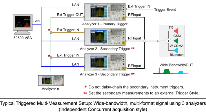
In this example, we will make a triggered multi-measurement on a wide bandwidth multi-format (GSM Global System for Mobile Communications: Originally developed as a pan-European standard for digital mobile telephony, GSM has become the world’s most widely used mobile system. It is used on the 900 MHz and 1800 MHz frequencies in Europe, Asia and Australia, and the 1900 MHz frequency in North America and Latin America., W-CDMA Code Division Multiple Access: One of several digital wireless transmission methods in which signals are encoded using a specific pseudo-random sequence, or code, to define a communication channel. A receiver, knowing the code, can use it to decode the received signal in the presence of other signals in the channel. This is one of several "spread spectrum" techniques, which allows multiple users to share the same radio frequency spectrum by assigning each active user an unique code. CDMA offers improved spectral efficiency over analog transmission in that it allows for greater frequency reuse. Other characteristics of CDMA systems reduce dropped calls, increase battery life and offer more secure transmission. See also IS-95., Bluetooth) test signal. This multi-measurement example includes three measurements, one for each signal format, using three independent analyzer configurations.
-
Set up the Hardware
-
Connect the primary trigger OUT signal to each secondary instrument's external trigger IN with a parallel connection (through a splitter).
Do not connect the instrument triggers in a series configuration (primary out to secondary 1 in, secondary 1 out to secondary 2 in, etc.). Connecting the trigger signal in a series configuration will degrade the synchronization accuracy.
- (optional) When using an external trigger signal to trigger the combination of measurements, connect the external trigger signal to the primary instrument's trigger IN.
-
-
Primary Trigger Setup
-
Specify the primary measurement:
Open the dialog and select for the measurement that is connected to the primary hardware.
-
(optional) Configure the primary measurement's trigger:
Select the primary measurement and then click and configure the settings as desired. You can leave the Style as if you want the primary instrument to trigger immediately after being armed.
-
-
Secondary Trigger Setup
-
Specify the secondary measurements:
In the dialog, clear the property for all measurements connected to secondary hardware.
-
Set all secondary measurements to an external trigger style:
Click and set Style to either or . Repeat this step for every concurrently runnable measurement whose property is cleared.
-
-
Start the triggered multi-measurement
In the dialog, click the Restart
 button to start all measurements.
The VSA begins the triggered multi-measurement process by first setting all secondary hardware into a waiting-for-trigger state (i.e. all secondary hardware is "armed"). Then the primary hardware is armed. When the primary hardware detects the trigger event, the primary hardware sends the trigger OUT signal, and all measurement hardware simultaneously begin to capture time data. This process effectively triggers all measurements to begin at a common trigger event (within the hardware trigger uncertainties).
Use the measurement controls toolbar on the dialog to perform a control operation on all concurrently runnable measurements (Restart, Pause, Record, Data From Hardware/Recording, and Continuous/Single Sweep).
Unsupported Measurement Hardware ("Trig Out" Functionality)
Certain measurement hardware models and/or functionality do not support the VSA multi-measurement capability. The following table contains some of the limitations:
| Measurement Hardware | Non-supported "Trig Out" Functionality |
|---|---|
|
Keysight ESA |
ESA instruments do not support the VSA's multi-measurement functionality. In addition, the ESA trigger input can't be used reliably with multi-measurements. |
|
Keysight PSA |
Wide-bandwidth channels (Option 122 or Option 140) do not support the VSA's multi-measurement functionality. |
|
Keysight X-Series Signal Analyzers |
is not supported in the following cases:
|
|
Note: This table is not a comprehensive list of all unsupported measurement hardware. Refer to the measurement hardware documentation for 89600 VSA "Trig Out" support. |
|
See Also
Available Properties and Controls