2 Channel RF, Dual X-Series Analyzer Configuration Measurement
This measurement procedure provides the basic steps to setup and make a 2 channel RF Radio Frequency: A generic term for radio-based technologies, operating between the Low Frequency range (30k Hz) and the Extra High Frequency range (300 GHz). measurement using a dual instrument configuration. A dual instrument configuration is a hardware analyzer configuration that consists of two compatible X-series analyzers. Not all X-series models can be used in dual instrument configurations, refer to the X-Series Custom Channel Configurations for details.
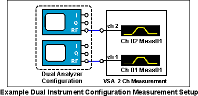
Dual Instrument Configuration Measurements
A dual instrument analyzer configuration is required to make a 2 Channel RF measurement; one analyzer for each measurement channel. Other supported dual instrument analyzer configuration measurements include: 1 & 2 channel RF, baseband 1 ch, baseband I & Q 2 channel, single channel I+jQ, and External Mixer channel measurements. For more information about supported X-Series analyzer hardware and measurements, see the Custom Channel Configurations topic.
Requirements for Dual Instrument Configurations:
- All instruments must be the same model and have the same firmware version and bandwidth option.
Prior to VSA 29.00, instruments were required to have the same frequency and capture memory options. Starting with VSA 29.00, that restriction has been removed, and the least common denominator of capture memory capability will be applied when using dual instruments.
Table 1. 2-Channel Measurement Minimum Software and Firmware Versions
| X-Series Instrument | Minimum Firmware Version | Minimum VSA Version | |
|---|---|---|---|
| N9042B | A.33.00 | 27.00 | |
| N9032B | A.35.05 | 28.00 | |
| N9010A and N9020A | A.02.00 (A.03.00 for improved time alignment) | 10.00 (11.00 for improved time alignment) |
For N9042B and N9032B, there may be significant delay between channels for this configuration. If triggering is used, the trigger delay for the second channel can be specified differently from the primary channel in order to time align the channels better.
2-Channel RF Measurement Procedure
This measurement procedure provides the basic steps fo make a 2 channel RF measurement.
- 2 Channel RF Measurement Hardware Setup
There are 2 measurement hardware setups; one for Remote PC operating mode (the 89600 VSA running in a PC) and one for Embedded PC operating mode (the 89600 VSA running in the X-series analyze):
• Remote PC Operation Measurement Setup
Make the hardware cable and I/O interface connections as shown in the X-Series Analyzer 2-Channel Measurement diagram..
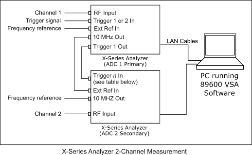
Table 2. ADC Analog-to-Digital Converter 2 Secondary Instrument Trigger In
X-Series Instrument
Trigger n In
N9042B Trigger 3 In N9032B Trigger 3 In Other X-Series Instruments Trigger 1 In Identify one X-series analyzer as the primary trigger hardware and the other as the secondary trigger hardware. Connect the 10 MHz Megahertz: A unit of frequency equal to one million hertz or cycles per second. Out from the primary X-analyzer to the Ext Ref In on the secondary X-series analyzer. Connect the Trigger 1 Out from the primary X-series analyzer to the Trigger n In (See Table 2 above) on the secondary X-analyzer. The primary X-series analyzer can optionally be locked to an external reference and have an external trigger input. The 10 MHz Out port of the secondary analyzer can be used to lock other system components.
The Trigger In signal on the primary X-series analyzer and the Ext Ref In on the primary X-Series analyzer are optional. The 10 MHz Out port of the secondary X-series analyzer can be used to lock other system components.
• Embedded PC Operation Measurement Hardware Setup
For Embedded PC operating mode, you need to setup and configure a LAN Local Area Network: A communications network that serves users within a local geographical area, typically over distances of around 100m. Wireless LANs use wireless communicaitons to network devices so there is no need for data cabling. interface between the primary and secondary X-Series analyzers. The X-Series analyzer that runs the 89600 VSA software is the primary trigger hardware.
Before running the 89600 VSA, open the Keysight Connection Expert software on the primary analyzer and configure a LAN interface connection to the secondary analyzer. You can also use the VSA software's integrated Instrument Manager to configure LAN interface connections.
For information on configuring for a LAN interface, see the Software Installation Guide. A crossover LAN cable is required for direct analyzer-to-analyzer cable configurations, see the Software Installation Guide for more information.
-
Start the 89600 VSA software.
• For Remote PC mode, start and run the Keysight 89600 VSA software program on the PC.
• For Embedded PC mode, start the 89601 VSA mode in the X-Series analyzer.
-
Create a Dual X-series instrument Analyzer Configuration.
- Open the New Hardware Configuration dialog box ( click ) and click the button
 . To create a new analyzer hardware configuration, do steps 1, 2, and 3 in the New Hardware Configuration dialog, see How to Create an Analyzer or Source Configuration.
 Do Step 1: Select the X-series analyzer from the list of Possible Logical Instrument list box and drag-and-drop it into the Configuration list box. This is analyzer number one in the dual instrument configuration.
- Repeat Step 1 to add the second X-Series analyzer to the dual instrument configuration. This will be the secondary analyzer.
Do Step 2:Select a X-series analyzer hardware from the ADC drop-down box that will be used for Logical Instrument 1 and a different analyzer for Logical Instrument 2 in this dual configuration.
Missing Hardware: Only X-Series analyzers that have an active VSA I/O interface will be included in the ADC drop-down box. Active hardware interfaces are listed in the Discovered Instruments dialog box. If the instrument is missing, make sure the hardware interface is properly connected using the IO Connection Expert utility and then refresh the list of VSA discovered instruments by selecting the Rediscover Instruments button in the Discovered Instruments dialog (> > > button).
- Do step 3: Name the analyzer configuration. You can accept the default name or create a custom name (double click in the text box to open the text editor).
- Click to apply changes.
- Specify the new Dual Analyzer Configuration as the VSA current measurement analyzer configuration. before closing the Hardware dialog, select the new analyzer configuration in the Current Analyzer Configurations drop-down box in the Hardware Configurations tab.
- Open the New Hardware Configuration dialog box ( click ) and click the button
-
Specify a 2 channel RF input channel type, click .
Custom Input Channel Configurations:When using the Input Channel Configuration dialog to specify or modify the input channel configuration mapping, only the VSA default set of channel configuration mappings are allowed; "invalid" channel configuration mappings are disallowed and the "" button is disabled "greyed out".
-
Configure the Hardware parameters
The X-Series hardware parameters a located in the Input Extensions dialog (). Review the hardware extension parameters and set them as required for your specific application, for more information see the X-Series "Input Extensions" topic.
-
Configure the Measurement Setup parameters.
Configure the input and measurement setup parameters for your particular measurement including: the range, the measurement type, center frequency, span, resolution bandwidth, trigger type, etc. Many X-Series hardware measurement parameters have unique functionality depending on the specific model and installed options. Before using the measurement setup parameters, review the X-Series Analyzer Measurement Setup Parameters topic for specific use and operating information.
Input Overload Condition
For 2-Ch Baseband measurement configurations, out-of-band input signals will cause an unexpected ADC Overload condition, ("OV" trace indicator) when the following conditions occur:
- The Out-of-Band signal frequency "fo" is greater than the current VSA measurement bandwidth (20 MHz maximum) but less than the maximum hardware analog input channel bandwidth (40 MHz). Therefore: VSA BW < fo < 40 Mhz.
- Out-of-Band signals are combined with the VSA Measurement In-Band signals to determine the range level. An unexpected range overload will occur when the additional Out-of-Band signals cause the combined VSA measurement range level to exceed the current VSA measurement setting.
This Range Overload condition may seem unexpected because the Out-of-Band signals are not shown on the VSA Trace window hiding the over range signals from view.
-
Calibrate the X-series analyzer.
Perform a system calibration before making a measurement, this will increase the measurement alignment and accuracy. See the Alignment/Calibration help in the Measurement Setup topic.
See Also