Single X-Series Analyzer Configuration Measurements
This measurement procedure provides the basic steps to setup and make a single instrument "X-Series Analyzer" configuration measurement. A single instrument configuration is a hardware analyzer configuration that contains only one X-Series analyzer, see Analyzer Hardware Configuration. Single instrument configurations can be used to make the following measurement types: 1 channel RF Radio Frequency: A generic term for radio-based technologies, operating between the Low Frequency range (30k Hz) and the Extra High Frequency range (300 GHz)., baseband 1 ch "I", baseband 2 channel "I & Q ", single channel I+jQ, and External Mixer channel measurements. For more information about supported X-Series analyzer hardware and measurements, see Custom Channel Configurations topic.
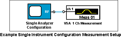
Single Instrument Configuration Supported Measurements:
Both the Embedded PC and the Remote PC operating modes support single instrument hardware configuration measurements.
Custom Input Channel Configurations:When using the Input Channel Configuration dialog to specify or modify the input channel configuration mapping, only the VSA default set of channel configuration mappings are allowed; "invalid" channel configuration mappings are disallowed and the "" button is disabled "greyed out".
System Requirements and Performance Specifications
The system requirements and performance specifications for using an
Keysight X-Series Signal Analyzer with the 89600 VSA are contained in the
technical overviews for each demodulation type. Links to these technical overviews are listed in the Product Literature topic. The technical overviews can also be downloaded from the ![]() 89600 VSA software web site.
89600 VSA software web site.
Single Instrument Measurement Procedure
This procedure provides the basic steps required to make measurements using a single X-Series analyzer configuration. Both the Remote PC and Embedded PC operating modes support single instrument configuration measurements. However, not all steps apply to both operating modes; differences are noted.
- Connect measurement setup hardware and cables. Use the Keysight Connection Expert software to establish an 89600 VSA to X-Series hardware I/O interface connection. You can also use the VSA software's integrated Instrument Manager to configure LAN Local Area Network: A communications network that serves users within a local geographical area, typically over distances of around 100m. Wireless LANs use wireless communicaitons to network devices so there is no need for data cabling. interface connections. See Remote PC Operation or Embedded PC Operation for more information.
- Start and run the 89600 VSA software
For Remote PC operating mode: start and run the Keysight 89600 VSA software program on the PC (see the Remote PC Operating mode topic ).
For Embedded PC operating mode: start the 89600 VSA by selecting the 89601 VSA mode in the X-Series analyzer (see the Embedded PC operation mode topic).Front Panel Control Lock-OutThe 89600 VSA software locks-out manual control of the X-Series analyzer front-panel keys while it is running. To get manual control of the analyzer front-panel, disconnect the 89600 VSA measurement -- select Disconnect will pause the measurement and release control of the analyzer. The analyzer can now be used independently from 89600 VSA. When the 89600 VSA measurement is resumed, the analyzer setup is restored to the pre-disconnect state.
-
Create a single X-Series instrument analyzer configuration.
-
Open the New Hardware Configuration dialog box ( click ) and click the button
 , see How to Create an Analyzer or Source Configuration.
 To create a new analyzer hardware configuration, do steps 1, 2, and 3 in the New Hardware Configuration dialog.
- Do Step 1: Drag-and-drop the Keysight X-Series Signal Analyzer from the list of hardware from the list box to the list box.
-
Do Step 2: From the ADC Analog-to-Digital Converter drop-down box, select the X-Series instrument (CXA, MXA, PXA, UXA, etc.) that will be used as the logical instrument in this analyzer configuration.
Missing Hardware: Only X-Series analyzers that have an active VSA I/O interface will be included in the ADC drop-down box. Active hardware interfaces are listed in the Discovered Instruments dialog box. If the instrument is missing, make sure the hardware interface is properly connected using the IO Connection Expert utility and then refresh the list of VSA discovered instruments by selecting the Rediscover Instruments
 button in the Discovered Instruments dialog.
 -
Do Step 3. Name the analyzer configuration. You can accept the default name or create a custom name (double click in the text box to open the text editor).
- Click to add new analyzer configuration and close the dialog box.
-
- Before closing the Hardware Configurations dialog, specify the new Analyzer Configuration as the current measurement Analyzer Configuration. Select the new configuration name in the drop-down box (Configurations tab).
-
Specify the input channel type ( RF, I+jQ, etc.) and the number of channels for your particular measurement, click select the input channel type > select the number of ).
The type and number of available input channels is determined by the X-Series hardware model and the installed options (refer to the X-Series Hardware Custom Channel Configurations measurement setup parameter topic).
Custom Input Channel Configurations:When using the Input Channel Configuration dialog to specify or modify the input channel configuration mapping, only the VSA default set of channel configuration mappings are allowed; "invalid" channel configuration mappings are disallowed and the "" button is disabled "greyed out".
BaseBand I+jQ measurements
All and measurements are only supported on X-series analyzers that have Option BBA Analog Baseband I/Q Inputs installed.
The channel type is a two-input I & Q measurement where the I and Q input waveforms are combined and analyzed as a single I+jQ channel measurement. In measurements, the span of the configured signal is double the span of the individual I and Q signals.
A signal overload on either of the I or Q channels causes an overload "OVx" condition error message on both channel traces. This condition caused by the mixing of the signals to create the BBIQ measurement and is not a fault of the hardware or software.
The Baseband BBIQ measurement supports all the basic VSA time, frequency, and statistical measurements as well as analog demod, flexible digital demod, and the supported standard-specific demod measurements. Additionally, BBIQ supports two-channel measurements such as frequency response, cross-correlation, and coherence.
-
Configure the Hardware Input Extension parameters.
The X-Series hardware parameters a located in the Input Extensions dialog (). Review the Input Extension parameters and set them as required for your specific application, for more information see the X-Series "Input Extensions" topic.
-
Configure the Measurement Setup Parameters.
Review the X-Series Analyzer Measurement Setup Parameters topic and configure the measurement setup parameters for your particular measurement including: the range, the measurement type, center frequency, span, resolution bandwidth, trigger type, etc.
-
Calibrate the X-Series analyzer.
Perform a system calibration before making a measurement, this will increase the measurement alignment and accuracy. See the Alignment/Calibration help in the Measurement Setup topic..
See Also