Subcarr IQ Mag Error (TEDS)
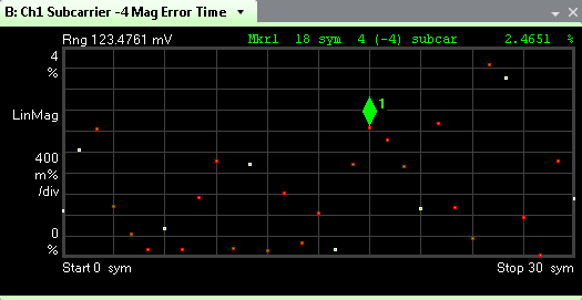
shows the IQ magnitude time error for the selected Analysis Subcarrier on a symbol-by-symbol basis. The image below is a Normal Uplink, 50kHz channel bandwidth, 16QAM modulation signal. The 31 vertical lines (0 to 30) represent the 31 symbols for the selected subcarrier in a Normal Uplink slot format.

Select to scale the trace. If the trace shows NO DATA, check your recorded signal or hardware input and your TEDS demod properties. TEDS demod parameters Droop and Pilot Tracking affect this trace. The above trace shows a LinMag (linear magnitude) scale. To change scales, see and choose from the format drop-down menu.
Select to place a marker on the trace; then review the symbol information in the marker readout window. Once you have a marker on the trace, use your left and right arrow keyboard keys to move the marker through the symbol points. The data symbol points are colored red and the sync, pilot, and header symbol points are colored white.
IQ magnitude error refers to the difference in the measured magnitude for an IQ phasor versus the magnitude of the ideal (reference) phasor, for a specified subcarrier.
To view a composite IQ Magnitude trace that incorporates all subcarriers, see Overlaid IQ Mag Error.
See Also
