About Measurement Interval and Offset (802.11b/g DSSS/CCK/PBCC)
Refer to DSSS/CCK/PBCC Preset to Standard table
The and parameters define a specific interval of the Result Length for demodulation and analysis. This feature is applicable to 802.11b/g Demodulation.
Specifies an interval (segment) of the Result Length data to be demodulated and analyzed. is entered in chips, which is rounded to the nearest whole number of data symbols, as determined from the input signals data rate and modulation format.
Sets the in Chips. determines the start position of the with respect to the first Chip of the PLCP Physical layer convergence protocol Preamble. is entered in chips, which is rounded to the nearest whole number of data symbols, as determined from the input signals data rate and modulation format.
The default measurement offset is set to 22 chips, which is 2 microseconds at the default chip rate. This is because the 802.11b and 802.11g specifications provide for up to 2 microseconds of ramp-up at the start of the burst. It is generally not desirable to include that ramp-up in the EVM Error vector magnitude (EVM): A quality metric in digital communication systems. See the EVM metric in the Error Summary Table topic in each demodulator for more information on how EVM is calculated for that modulation format. calculations.
Specific time intervals of data can be quickly analyzed and viewed with this feature. This is because the VSA does not acquire new measurement data when the measurement interval or offset is changed. When a new measurement interval or offset is entered the VSA re-computes the trace data results using the existing measurement data.
Trace Data Results
The and affect nearly all measurement results, including the Preamble Syms and Header Syms trace data, and the region over which EVM is calculated. The only trace data not affected by and are the Error Summary values for Sync Correlation, Frequency Error, Burst Type, Bit Rate, Octets, and Data Length. The "802.11-2007 1000 chip Peak EVM" is computed from the first 1000 chips starting at the Measurement Offset.
The following illustration shows the interrelationship between the , Result Length, , and .
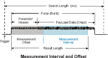
The Time trace display shows only time data for the chips specified by the parameter, except when the plus is equal to . In this case, the Time trace display includes the burst data +/- 10 % on either side of the burst. Refer to Time trace data for complete details.
-
Result Length: Total number of chips included in the acquired and demodulated data.
-
Maximum Result Length Sets the maximum number of chips that can be included in the result length. limits the to the number of chips within the pulse (or burst).
See Also