Time (802.11b/g DSSS/CCK/PBCC)
When 802.11b/g DSSS Direct sequence spread spectrum. The data transmission scheme (sometimes referred to as a "'modulation" scheme) used in 802.11b WLANs. DSSS uses a radio transmitter operating at a fixed centre frequency, but using a relatively broad range of frequencies, to spread data transmissions over a fixed range of the frequency band. 802.11a and 802.11g (when not operating in 802.11b mode) use Orthogonal Frequency Division Multiplexing (OFDM)./CCK complementary code keying/PBCC packet binary convolutional code Demodulation is enabled, the trace shows the time record before digital demodulation and after pulse search, as shown in the following block diagram (refer to the Digital Demodulation Block Diagram).

The amount of data included in the trace display is a function of the Result Length, , and parameters. The following topics describe how these parameters affect the Time trace data:
Time Reference
The time reference for the time data is the idealized start of the PLCP Physical layer convergence protocol preamble. If the preamble uses the long format, this means that the PLCP Header will start at time = 144us and the PSDU 1) PHY Service Data Unit, or 2) PLCP SDU data will start at time = 192us. If the preamble uses the short format, this means that the PLCP Header will start at time =72us and the PSDU data will start at time = 96us.
It may be useful to zoom in on the ramp up at the start of the burst, by setting the X axis to display from time = -10us to time = +10us. This results in grid lines spaced 2us apart. The ramp up should take less than 2us and should be near the middle of this display.
Time Trace Data and the Result Length parameters
-
Automatic mode: The Trace data shows the data specified by parameter:
-
If Maximum Result Length is less than the burst length, the trace data shows the number of Chips specified by the parameter plus 10% of the parameter just before the start of the burst. This also includes preamble data.
-
If is greater than the burst length, the trace data shows the entire burst +/- 10% of the burst length.

-
-
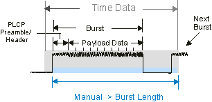
Manual mode: The Trace data shows data for the number of symbol-times specified by the parameter plus 10% of the parameter just before the start of the burst.

For more information about how the parameter determines the measurement result length data, see About Result Length.
Time Trace Data and the Measurement Interval/Offset parameters
-
not equal to
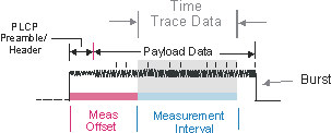
When the Measurement Interval and Offset parameters are used to specify the acquired measurement data, the trace data includes only the data specified by the Measurement Interval parameter. The display shows only data for the symbol-times specified within the , all other data before and after the will be excluded.

-
equal to
When the is equal to , the trace data is controlled and specified by the parameter. See Automatic mode described previously for more information.
For more information about how and determine the measurement result length data, refer to Measurement Interval and Offset.
See Also
