VVM Mode (Option 308) measures the electrical length of cables and other devices. The 1-Port Cable Trimming and 2-Port Transmission measurement displays the electrical length in both Magnitude and Phase.
Figure 25-1 Display for the 1-Port Cable Trimming measurement
In this Chapter
Procedures
In the FieldFox, both 1-port and 2-port measurement types use a different configuration setup from the HP/Keysight 8508A Vector Voltmeter.
Figure 25-2 Typical 8508A measurement configuration –as shown in the 8508A manual.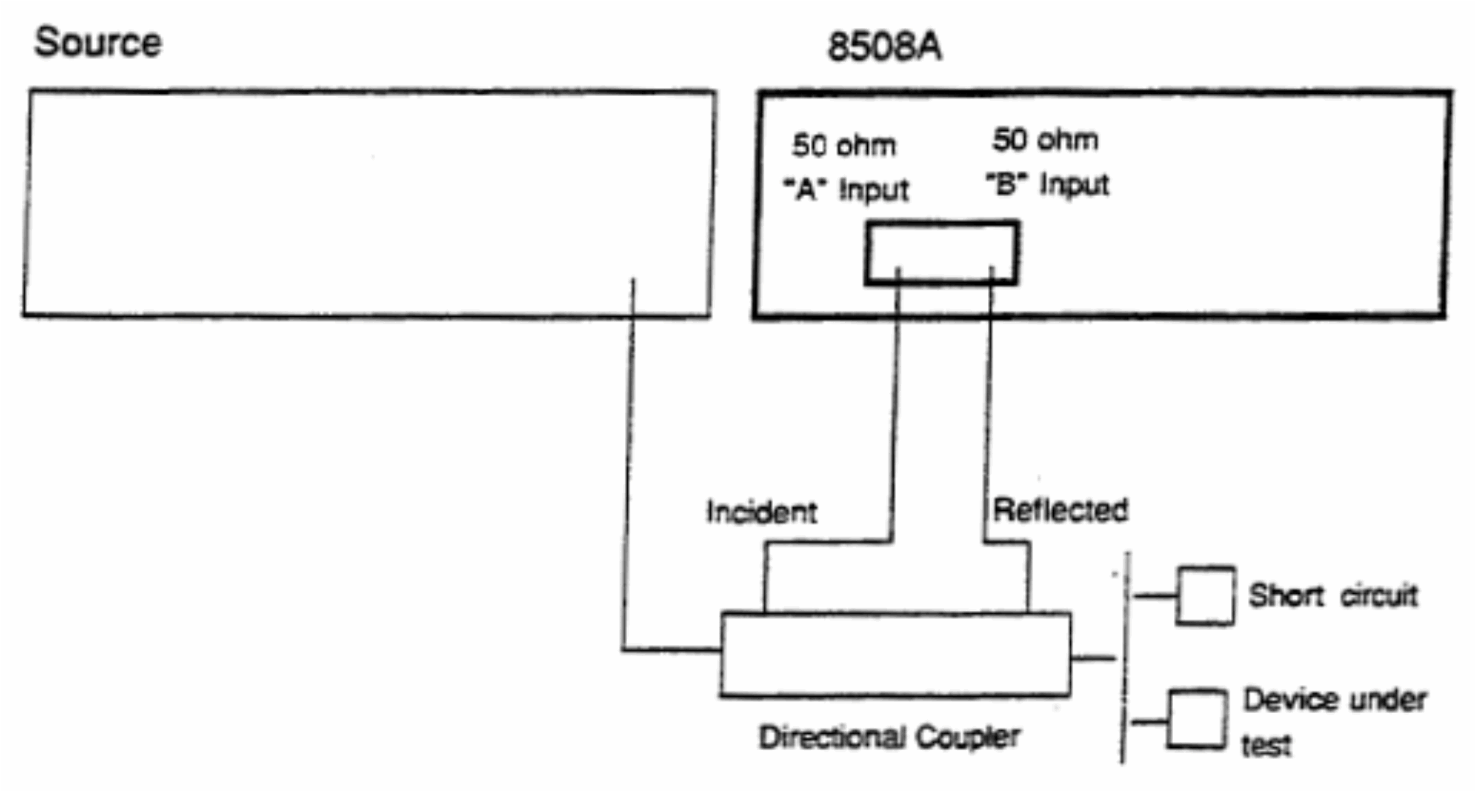
The above block diagram requires an external source and directional coupler to measure the electrical length of a DUT or cable to be trimmed. Separate paths are used to measure the Incident signal (A) and Reflected signal (B). To measure the ratio of the Reflected/Incident signals, you were required to select B/A for both the Magnitude and Phase display.
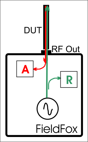
In the FieldFox, the source and directional coupler are inside the instrument. This allows you to connect the DUT to ONLY the FieldFox PORT 1, with NO external instruments, in order to make Cable Trimming measurements.
See the FieldFox block diagram and Cable Trimming procedures beginning in “1-Port Cable Trimming Measurements ” on page 691.
Select VVM Mode before making any setting in this section.
How to select VVM Mode
—Press Mode
—Then VVM
How to select a VVM Measurement
—Press Measure 1
—Then choose from the following:
—1-Port Cable Trimming 1-port reflection measurement. Learn how to make this measurement in “1-Port Cable Trimming Measurements ” on page 691.
—2-Port Transmission 2-port transmission measurement. Learn how to make this measurement in “2-Port Transmission Measurements” on page 693.
—B/A and A/B 2-port ratioed receiver measurements using external sources. Learn more in “A/B and B/A Measurements” on page 694.
How to set Frequency
—Press Freq/Dist
—Then Frequency
—Enter a value using the numeric keypad, the  arrows, or the rotary knob.
—After using the arrows or the rotary knob, press Enter. The increment setting of the arrows is based on the current span and can NOT be changed in VVM Mode.
—After using the keypad, select a multiplier key. Learn about multiplier abbreviations in“Multiplier Abbreviations” on page 53.
You can display either one digit or two digits after the decimal point for both magnitude and phase readings.
This setting survives a Preset and Mode Preset.
How to set Resolution
—Press Scale/Amptd
—Then Resolution
—Then choose:
—1 0.0 (default)
—2 0.00
Reducing the IF receiver bandwidth reduces the effect of random noise on a measurement. However, narrower IF bandwidths cause longer measurement times.
For highest accuracy, Zero AFTER changing the IF Bandwidth. Learn about Zeroing in “Zeroing” on page 689.
How to set IF BW
—Press BW 2
—Then IF BW
—Then choose from the following:
—10 Hz | 100 Hz | 1 kHz | 10 kHz | 100 kHz
More 30 Hz | 300 Hz | 3 kHz | 30 kHz
Set the power level out of the FieldFox to High, Low, or manually set power level to a value between High and Low.
Generally, the high power setting is used when measuring passive, high-loss devices to place the signal farther from the noise floor. Increasing the power can also help reduce trace noise. However, for devices that are sensitive to high power levels such as amplifiers, use the Low power setting.
For best measurement accuracy, use the Manual power setting at -20 dBm. After calibration, the power level can be decreased for amplifiers, or increased for higher dynamic range.
| Power Level settings in this mode will NOT change Power Level settings in other modes. To help prevent damage to your DUT, use caution when changing modes with your DUT connected to the FieldFox test ports. |

| For consistency with other FieldFox A/B models (backward compatibility), the default Output Power is set to –15 dBm. To avoid overload when using FieldFox C model, users should manually change the Output Power setting to –20 dBm. |

—Press Meas Setup 4.
—Then More
—Then Output Power
—High Sets output power to the maximum achievable power at all displayed frequencies. Output power is NOT FLAT across the displayed FieldFox frequency span. Use the High power setting, when better dynamic range and lower noise is desired. Please see “Specifications/Data Sheet” on page 979 for expected power levels.
—Low Sets output power to approximately –50 dBm.
—Man (Default setting) Sets the output power to –15 dBm, FLAT across the displayed FieldFox frequency span. If flattened power can NOT be achieved, a warning message and beep occurs. To achieve a flattened output power, reduce the power level or stop frequency.
—Then press Power Level
—Then enter a value using the numeric keypad, the arrows, or the rotary knob.
—Press Enter.
Averaging helps to reduce the effects of random noise on a measurement. The FieldFox computes the displayed value over several consecutive readings. Average count determines the number of readings to average. The higher the average count, the greater the amount of noise reduction.
An average counter is shown in the left edge of the screen as Avg N. This shows the number of previous readings that have been averaged together. When the counter reaches the specified count, then a ‘running average’ of the last N readings is displayed.
Average count = 1 means there is NO averaging.
This setting can be changed at any time without affecting calibration accuracy.
How to set Averaging
—Press Meas Setup 4
—Then More
—Then Avg N where N is the current count setting.
—Enter a value using the numeric keypad. Enter 1 for NO averaging.
—Press Enter.
To restart the averaging process, press Meas Setup 4, then More, then Restart
This setting determines whether the FieldFox measures continuously or only once each time the Single button is pressed. Use Single to conserve battery power or to allow you to save or analyze a specific measurement.
This setting can be changed at any time without affecting calibration accuracy.
How to set Single or Continuous
—Press Meas Setup 4
—Then choose one of the following:
—Single Automatically sets Continuous OFF and causes the FieldFox to make ONE measurement, then hold for the next Single key press. The Hold annotation changes to an arrow --> while the measurement occurs.
—Continuous OFF and Hold both put the FieldFox in Hold mode.
—Continuous ON Makes continuous measurements. This is the typical setting when battery power is not critical.
—You can also use Run / Hold +/- to toggle between Single and Continuous.
CalReady is accurate for most zeroed VVM measurements at frequencies below about 6 GHz. For the very highest accuracy, especially above 6 GHz, then perform a Mechanical Cal. Learn more in “How to Perform a Calibration” on page 134.
Press Zero OFF before calibrating (sets Zero to OFF).
Zeroing, also known as Normalization, or Data/Memory, simply “Zeroes” the Magnitude and Phase display when Zero ON is pressed. All subsequent measurements are relative to the measurement that was made when Zero was pressed.
When an instrument state is saved with Zero ON, the zeroing data is saved with the state file, similar to how a calibration is saved with a state file.
—When performing a 1-Port Cable Trimming operation, a reference cable is connected and measured. Then Zero is pressed, and subsequent cables are measured and trimmed to match electrical length of the reference cable.
—For 2-port measurements, Zero is typically pressed when a THRU connection is made in place of a DUT. Learn more in “2-Port Transmission Measurements” on page 693.
Press Zero OFF before performing a Mechanical Cal (sets Zero to OFF).
How to select Zeroing
—Press Meas Setup 4
—Then Zero Ref
—Open – select to display Phase = 0.0 Deg when zeroed.
—Short - select to display Phase = 180.0 Deg when zeroed.
—Then Zero ON
—Select Zero OFF to turn zeroing off.
1-Port Cable Trimming Measurements
A 1-Port Cable Trimming measurement is used in a cable fabrication procedure to validate proper electrical length.
| —The R receiver measures incident signal (green line) out of the source. —The A receiver measures reflected signal (red line) from the end of the DUT (black line). — In VVM mode, the display ALWAYS shows ratioed (A/R) measurements which is the electrical length of the DUT. |
How to make a 1-Port Cable Trimming Measurement
1.Press Mode then VVM then 1-Port Cable Trimming.
2.Press Freq/Dist then enter the frequency for the measurement.
3.To improve measurement stability, change the IF Bandwidth, Output Power, and Averaging settings as needed.
4.4. Press Meas Setup 4 then Zero OFF.
5.Optionally calibrate the FieldFox. Learn more about VVM calibration in “VVM Calibration” on page 689.
6.To ensure that the calibration is adequate, perform the following optional Measurement Verification procedure.
| This measurement verification procedure is suitable for low frequency measurements. However, for high frequency measurements, a more sophisticated procedure is required. |
a.Connect a short standard to PORT 1 where cables to be trimmed will be connected.
b.Press Meas Setup 4 and press Zero.
c.Remove the short standard and connect the open standard.
d.Confirm that magnitude measurement is less than –0.1 dB and that the phase value reads 180° degrees.
7.Attach the shortest cable to the FieldFox PORT 1 connector. This cable is the reference cable. Leave the end of the reference cable open (unterminated).
8.Press Meas Setup 4 then press Zero.
9.Remove the reference cable from the FieldFox PORT 1 connector.
10.Connect an unterminated, longer cable to the FieldFox PORT 1 connector.
11.Observe the displayed phase difference between the reference cable and the untrimmed cable.
| The VVM phase reading shows a maximum of ±180°. Therefore, the electrical length of the untrimmed cable MUST be within 180° of the reference cable. |
12.Carefully trim the cable until the phase shift reads zero. The attached cable’s electrical length is now matched to the reference cable.
13.Repeat steps 10 through 12 for the remaining cables to be trimmed.
2-Port Transmission Measurements
A 2-Port Transmission measurement is used for measuring electrical length, insertion loss, gain, or isolation of a DUT at a single CW frequency. The FieldFox signal source is transmitted out the port 1 connector, through the DUT, and into the port 2 connector. In the following image, the gain of an amplifier is being measured.
Figure 25-3 2-Port Transmission measurement of an amplifier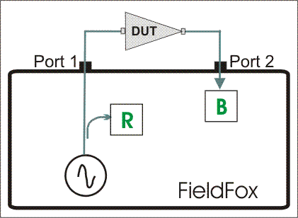
How to make a 2-Port Transmission Measurement
1.Press Mode then VVM then 2-Port Transmission.
2.Press Freq/Dist and enter the measurement frequency.
3.Press Meas Setup 4 then More then Output Power. Select High for passive devices. Select Low for amplifiers.
4.Calibrate the FieldFox using one of the methods described in “VVM Calibration” on page 689. Before performing a Mechanical Cal, press Meas Setup 4 then Zero OFF.
5.Connect the DUT.
Notes:
—The magnitude value is the gain (positive value) or the loss (negative value) of the DUT.
—The phase value is the difference in phase (in degrees) between the DUT input and output.
—To measure isolation of the amplifier, reverse the connection to the amplifier (PORT 1 to the amplifier output).
These measurements allow you to use the FieldFox A and B receivers, along with an external source, to make ratioed measurements.
| These measurements require the “Full 2-port S-parameters” option. |
The image below shows a typical configuration for a B/A magnitude and phase measurement of a 2-port DUT. This DUT can be an antenna / probe setup. Using network analyzer terms, the image shows the A receiver as the reference receiver which measures the signal that is applied to the DUT. The B receiver is the test port receiver which measures the DUT response.
Figure 25-4 B/A Transmission measurement with external source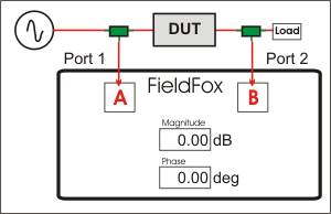
Procedure
1.Connect the external source’s frequency reference output to the FieldFox Freq Ref IN on the top panel. If you are unable to use a common frequency reference, then increase the IFBW to ensure you are measuring the peak of the correct signal. After locating and tuning to the signal, you may be able to lower the IFBW to reduce noise.
2.On the FieldFox, select System 7, then System Configuration, then Frequency Ref, then Freq Ref Source then Ext.
3.Press Mode, then VVM , then B/A or A/B
4.The FieldFox internal source is NOT used, so the output power setting is not relevant.
5.To calibrate, replace the DUT with a THRU connection, preferably by connecting together the two Power Splitters (shown in green). For low frequency measurements, TEEs can be used.
6.Press Meas Setup 4, then Zero.
7.Connect the DUT and measure.