8Calibration for NA, CAT, and VVM Modes
Calibration removes the systematic errors that are associated with measurements in NA, CAT, and VVM Modes. Key presses are identical in all of these Modes.
In this Chapter
See Also
Learn How to Make 75 ohm Measurements at the FieldFox Supplemental Online Help: https://rfmw.em.keysight.com/wireless/helpfiles/FieldFoxOnlineSupplementalHelp/Home.htm.
Comprehensive Guide for Calibration
There are well-defined and understood systematic errors that are measured and calculated during the calibration process. These errors are caused by leakage signals inside the FieldFox, by the frequency response of the FieldFox receivers, and by reflections inside the FieldFox that interact with the DUT. After calibration, these errors are removed from subsequent measurements.
To maintain highest measurement accuracy, perform a new calibration when any of the following changes occur:
—When any of the following measurement settings change: Frequency Range, Power Level, IF BW, and Resolution. Therefore, make these measurement settings before calibrating. Increased Averaging, lower IF BW, and higher Resolution all cause slower sweeps and slower calibration times. Learn about Interpolation and Questionable Accuracy in “Interpolation *” on page 149.
—When the FieldFox temperature changes more than about 10°F (5°C). Learn more in “How to monitor the internal FieldFox temperature:” on page 36.
—When the connection to the DUT changes, requiring a different jumper cable or adapter.
DUT (Device Under Test) The cable, antenna, transmission line, amplifier, or anything else that is connected to the FieldFox that is to be measured.
Calibration Standards - OPEN, SHORT, LOAD, and THRU
—OPEN, SHORT, and LOAD are ‘reflection’ standards that are used during calibration. When an RF signal ‘hits’ these components, the signals are reflected in a predictable manner. These components can also be used to terminate a DUT port during some measurements.
—SHORT and OPEN standards both cause 100% of an RF signal to be reflected. The difference between these two standards is what happens to the phase of the reflected signal, which is beyond the scope of this discussion. Although an OPEN standard is a precision component, simply leaving nothing connected at the end of a cable can be a reasonable substitute for an OPEN.
—A LOAD standard absorbs almost ALL of the incident signal and very little signal is reflected back to the source.
—A THRU standard is used during some calibration steps to connect PORT 1 to PORT 2 in place of the DUT. A Flush THRU connection can be made when cables that connect with the DUT can mate with each other. Learn more in “Mechanical Cal” on page 136. Otherwise, any reasonably short cable can be used as a THRU standard.
Calibration Reference Plane is the point (or points) at which the DUT and cal standards are connected during a calibration. This can be at the FieldFox test port connectors, or at the end of jumper cables or adapters.
Every FieldFox contains a factory calibration that was performed at the port 1 and port 2 connectors, with –15 dBm input power, over the entire frequency range of the FieldFox using a number of data points that allows reasonable interpolation over the FieldFox frequency range.
This calibration, known as CalReady, allows you to immediately make measurements of a DUT that is connected directly at the test ports (PORT 1 and/or PORT 2). CalReady corrects measurements when the FieldFox is turned ON and when a measurement is created with no other correction in place.
When measuring a DUT using a jumper cable or adapter - NOT a direct connection to a test port connector – then a Mechanical Cal is recommended. CalReady can also be used to check the integrity of the jumper cable that is attached to the test ports.
CalRdy is shown when a measurement is corrected using CalReady.
You can change the properties of the CalReady calibration. Learn more in “CalReady” on page 134.
Learn how to see when your factory CalReady calibration was performed in “System Information” on page 903.
Press Esc at any time to end the calibration process. When performing a calibration that contains a large number of points (5000 to 10,001 points) be aware that the calibration progress bar may not move for 2 or 3 minutes during the calibration process. |
In CAT, NA, or VVM Mode, press Cal 5.
The following appears:
Choose Calibration Method screen
—Response Cal – Used to quickly calibrate ONE type of measurement using mechanical standards. Measurement accuracy is generally low. Learn more in “Simple Response Cals” on page 141.
—Mechanical Cal/ECal – Using mechanical cal standards from a cal kit, perform an accurate calibration at one or both test ports, adapters, or jumper cables. Full 2-port mechanical calibration is the most accurate calibration available with FieldFox. Learn more in “ECal” on page 138.
—User Cal OFF ON – Turns ON and OFF the effects of the user calibration that you performed. The OFF state reverts to CalReady.
—View Cal – Shows the properties of the current calibration. Learn more in “View Cal” on page 143.
—More – Learn about Cal Ready Properties in “CalReady” on page 134.
| Source Unleveled errors - During calibration, the frequency range of the measurement MAY be extended to provide maximum flexibility. During the calibration, the output power may become unleveled at the added high frequencies. You can ignore the “Source Unleveled” error, or to avoid the error, select either High power or –15 dBm before calibrating. Learn more about setting Output Power in “Output Power” on page 63. |

Mechanical Calibration is performed using discrete standards from a Cal Kit. Several Cal Kit definitions are built into the FieldFox. To learn about Cal Kit definitions, refer to the Application Note, “Specifying Calibration Standards and Kits for Keysight Vector Network Analyzers,” available online at https://www.keysight.com/us/en/assets/7018-01375/application-notes/5989-4840.pdf.
| Visit www.keysight.com/find/fieldfoxsupport to see a complete list of supported Cal Kits. Also at this website, download Data-Link software that allows you to edit Cal Kit definitions or add a new Cal Kit. |
Mechanical Cals are extremely accurate when performed using the correct Cal Kits with standards that are clean and in good repair, and when using correct connection procedures.
How to perform a Mechanical Cal
—Disconnect the DUT from the FieldFox.
—If a jumper cable or adapter is required to connect the DUT to the FieldFox, then connect those components to the FieldFox connectors. The effects of those components will be measured and removed during the calibration, and only the effects of the DUT will be displayed in the measurement results. These should be high-quality components!
—In NA, CAT, or VVM Mode, press Cal 5.
—Then Mechanical Cal 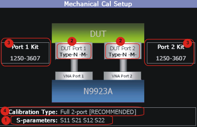
This page summarizes the Mechanical Cal to be performed and allows you to make changes. For best results, review the screen and make changes in the following order:
1.S-parameters – Verify that these are all of the S-parameters that you want calibrated. If not, press Esc to terminate the calibration process, then return to the Trace menu to display all of the traces to be calibrated. Learn how in “Multi-Trace Configurations” on page 101
2.DUT Connectors – For each DUT port that is shown, verify the correct type and gender of the DUT connector. If a DUT port is not shown, then that port is not included in the list of S-parameters to be calibrated.
3.Cal Kit - Verify the correct Cal Kit for each DUT port to be calibrated. See a list of supported Cal Kits in the FieldFox Data Sheet. Learn more in Appendix B: “Specifications/Data Sheet,” on page 979.
If the DUT connector type, gender, or Cal Kit is NOT correct for the DUT ports to be calibrated, then:
—Press Change DUT Connectors to select the correct connector types that are on your DUT.
—For each port:
—Use the  arrows or rotary knob to change the DUT connector type.
—Press Change Gender to change the gender of the DUT connector.
—Then press Next… to confirm the selection and continue the process.
—For each port:
—Use the arrows or rotary knob to select the Cal Kit that you have, and are going to use, for the specified ports.
—Press Next… to confirm the selection and continue the process.
—Then press Finish to end the selection process.
4.Calibration Type - The FieldFox always RECOMMENDS a Cal Type that will quickly and accurately calibrate all of the displayed S-parameters. Change from the RECOMMENDED Cal Type ONLY if you understand the implications. Learn more about Cal Types in “Calibration Type” on page 143.
To select a different Cal Type:
—Press Change Cal Type.
—Then using the arrows or rotary knob, select a Cal Type,
—Then press Select and Finish.
Begin Calibration
1.Press Start Calibration.
| If an error appears (“Failure to compute calibration steps…”), check to ensure that the frequency range of the Cal Kit covers the frequency range of the measurement. You can verify the frequency range of your Cal Kit at: www.keysight.com/find/fieldfoxsupport. Click Cal Kits. |
2.Follow the Cal Wizard prompts. Connect the specified standard at the point where the DUT will be connected, then press Measure.
3.At any time, press Back to re-measure a standard if you feel it was not properly connected.
4.Press Finish to complete the calibration.
CAL ON U is shown on the screen for all displayed measurements that are corrected with the Mechanical Cal.
ECal

ECal is a complete solid-state calibration solution. Every ECal module contains electronic standards that are automatically switched into position during a calibration. These electronic standards have been measured at the factory and the data stored within the memory of the ECal module. The FieldFox uses this stored data, along with the measured data, to calculate the error terms for a measurement calibration.
You can perform the following calibrations with ECal:
—1-Port Reflection calibration
—Full 2-Port calibration
All Keysight USB ECal modules are supported. ECal modules are available in a variety of connector types, covering many frequency ranges. For information about available ECal modules, see http://www.keysight.com/find/ecal
Select an ECal module that has connectors of the same type and gender as the DUT. If such an ECal module is not available, a module with connectors different from the DUT can be used by selecting a User Characterization. This selection is located on the Mechanical Cal Setup page of the CalWizard. However, a User Characterization can NOT be PERFORMED using the FieldFox. It must be performed using a bench top Keysight VNA, such as the PNA or ENA. Learn more about user characterizations by referring to “User-Characterization” in the PNA Help https://rfmw.em.keysight.com/wireless/helpfiles/N52xxB/help.htm.
How to Perform a Calibration Using ECal
1.Make measurement settings on the FieldFox (frequency range, number of points, etc.)
| The frequency range of the measurement MUST be within the frequency range of the ECal module or an error will appear when “Calculating Steps” during the calibration. |
2.Connect the ECal module USB cable to the FieldFox USB.
3.Allow the module to warm up until it indicates READY. This may take several minutes.
4.Connect the ECal module ports to the FieldFox at the calibration reference plane (where the DUT will be connected).
5.Press Cal 5 to start the Calibration.
6.Press Mechanical Cal / ECal
7.Press Change DUT Connectors. For each test port to be calibrated, select the Connector Type and Gender of the DUT / ECal module. The connected ECal module and relevant User Characterizations will appear, with the ECal factory default as the default Cal Kit.
8.Optionally press Advanced then ECal Auto Orient.
—ON (default) The FieldFox automatically senses the direction in which the ECal module ports are connected to the FieldFox ports.
—OFF If power to the ECal module is too low, it cannot detect which FieldFox ports it is connected to. If you are having this problem, select OFF. Then during the calibration, the FieldFox will prompt you to connect the ECal module ports to specific FieldFox ports.
9.Optionally press Advanced then Extended Cal.
—ON The FieldFox Extended Cal measures additional points outside the current frequency range in order to enable adjusting the frequency range after the calibration procedure. With these extra points, the error correction may be applied when it otherwise might not. Without extended cal, if you adjust your frequency outside the calibrated range after the calibration has been completed, the error correction is turned off.
—OFF (default) The FieldFox does not measure any frequency points outside the current displayed frequency range. If the frequency is adjusted outside of the set of points calibrated the error correction is turned off and the following message is displayed:
"Error correction disabled. Stimulus outside calibrated range."
10.Press Start Calibration. When prompted, verify the ECal module connection, then press Measure. The standards within the ECal module are automatically connected and measured.
Simple Response Cals are used to quickly calibrate the magnitude and phase of a measurement using any Open, Short, or Thru component. These may be calibration standards, but because a Cal Kit is not selected, they are not modeled. Measurement accuracy is generally low. Use a Simple Response Cal to make quick measurements when using a jumper cable to connect the DUT to the FieldFox. Otherwise, CalReady is usually more accurate.
| You can perform a Simple Response Cal for either: S11, or S22, or S21 AND S12. |
When prompted, choose a standard based on the displayed measurements to be calibrated. For example, to calibrate S11, connect either an OPEN or SHORT to the port 1 reference plane.
When Simple Response Cals are performed, the source match and reflection tracking terms from CalReady are updated by the measured Short or Open that is used during the calibration.
1-port response cals are also available from the Mechanical Cal menu. Learn more in “Calibration Type” on page 143.
Normalize uses a THRU standard or cable between port 1 and port 2 to cal an S21 and S12 Transmission measurement (NA Mode) and a 2-port Insertion Loss measurement (CAT Mode). In VVM Mode, this is performed using Zero.
When a Normalization is performed, the forward and reverse transmission tracking terms from CalReady are updated to account for the THRU that is used during the normalization process.
How to perform a Simple Response Cal
1.Select the measurements to be calibrated. See the relevant Mode (NA, CAT, or VVM) for measurement selections.
2.Press Cal 5 then Response Cal
3.For 1-port measurements:
—Select either Open Response or Short Response for the port to be calibrated. The availability of this calibration on Port 2 may require an option.
—Connect an OPEN or SHORT standard to the specified port and press Measure
4.For 2-port measurements:
—Select Normalization
—Connect a short, high-quality, phase stable cable between the FieldFox port 1 and port 2 connectors, then press Measure
With a Normalization Cal, all subsequent insertion loss measurements are made relative to the insertion loss of the cable used as the THRU standard. For example, if you use a cable with 1 dB of loss, then after Normalization, the display will show 0 dB of loss with this cable in place. Therefore, for highest accuracy, when measuring the DUT also attach the cable that was used in the normalization cal. |
5.Press Finish.
6.Connect the DUT.
CAL ON U is shown on the screen when a User Cal (Ex: Response Cal) is correcting ONLY the appropriate measurement. For example, when an Open Response Cal on Port 2 is performed, CAL ON U is shown for an S22 measurement only.
From the Choose Calibration screen (see “How to Perform a Calibration” on page 134), press View Cal to see the following screen: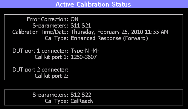
The top box shows the properties of the current calibration that you performed and the displayed S-parameters that it is correcting.
The bottom box shows the S-parameters that are displayed but NOT corrected by the current performed calibration, but rather the CalReady calibration. Learn more about CalReady in “CalReady” on page 134.
The FieldFox simplifies the calibration process by recommending the most accurate and efficient calibration type based on the displayed S-parameters.
However, there may be times when you may want a little more accuracy or a little faster sweep time. The following information can help you learn about the various calibration choices.
Definitions:
|
|
|---|---|
Non-insertable DUT – A device whose connectors could NOT mate together. They either do not have the same type of connector or they have the same gender. This also means that the test port cables could NOT mate together as in the above diagram. | Insertable DUT – A device whose connectors could mate together. They have the same type of connector and opposite or no gender. This also means that the test port cables could mate together, as in the above diagram. |
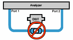
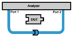
Defined THRU – A THRU standard for which there is a Cal Kit definition such as in the 8551xA Cal Kits.
Flush THRU (also known as Zero length THRU) – When the test port cables mate together when measuring an Insertable DUT. No actual THRU standard is required because the test port cables are directly connected. Flush THRU is also a Defined THRU with a definition of zero loss and zero length.
Unknown THRU - Any THRU connection between the test ports. For more information see the FieldFox Supplemental Online Help: https://rfmw.em.keysight.com/wireless/helpfiles/FieldFoxOnlineSupplementalHelp/Home.htm.
Sweep Directions – Both FULL 2-Port Cals listed below result in correction that requires background measurements sweeps in both directions, regardless of the displayed measurements. The displayed traces are updated at a slower rate than Enhanced Response and 1-port calibrations, which require sweeps in one direction only.
1-Port (OSL)
DUT: No restrictions
S-parameters Corrected: S11 or S22
Standards: OPEN, SHORT, LOAD
Sweeps in ONE direction.
FULL 2-Port (May require an option)
Most comprehensive calibration. Corrects all S-parameters
DUT: Non-Insertable or Insertable
Standards: OPEN, SHORT, LOAD on BOTH ports. Any THRU between ports.
Based on the SOLR/Unknown THRU calibration. For more information on the Unknown THRU process, see the FieldFox Supplemental Online Help: https://rfmw.em.keysight.com/wireless/helpfiles/FieldFoxOnlineSupplementalHelp/Home.htm.
Sweeps in BOTH directions.
FULL 2-Port (QSOLT) – Mechanical Cal ONLY (May require an option)
Quicker to perform QSOLT than Full 2-port. Corrects all S-parameters.
DUT: Insertable only
Standards: OPEN, SHORT, LOAD on port 1. Flush THRU between ports.
Recommended cal type for Insertable DUTs. A Cal Kit is NOT required for port 2.
Sweeps in BOTH directions.
Enhanced Response Cal - Forward OR Reverse (May require an option)
Faster measurements than Full 2-Port.
DUT: Non-Insertable or Insertable. S-parameters PARTIALLY Corrected: S21 and S11 (Forward) OR S12 and S22 (Reverse)
Standards: OPEN, SHORT, LOAD on ONE port. Defined or Flush THRU between ports.
Sweeps in ONE direction.
| Also select an Enhanced Response Optimization. Learn more in “Enhanced Response Optimization” on page 148. |
A complete 2-Port calibration with potentially better accuracy than Full 2-port. Corrects all S-parameters.
DUT: Non-Insertable or Insertable
Standards: Thru, Reflect, Line or variations of these. A TRL Cal Kit MUST be selected to see this Cal Type
Sweeps in BOTH directions.
Learn more about TRL Calibration in the Supplemental Online Help: https://rfmw.em.keysight.com/wireless/helpfiles/FieldFoxOnlineSupplementalHelp/Home.htm.
1-port Response Cals (Open or Short)
Calibrate the magnitude and phase of a measurement using ‘modeled’ mechanical standards. Measurement accuracy is better than Simple Response Cals (available on the main Cal page - see “Calibration Type” on page 143) but NOT as good as full 1-port cal. Corrects either S11 or S22. Can be used with Isolation (see following section). Learn more in “Simple Response Cals” on page 141.
DUT: Non-Insertable or Insertable
S-parameters Corrected: S11 or S22
Standards: OPEN or SHORT on ONE port
Sweeps in BOTH directions.
The optional isolation step of a calibration corrects for crosstalk which is the internal signal leakage between the test ports. The Isolation step measures Load standards that are connected to one or both FieldFox test ports.
Perform an isolation calibration when you are testing a device with high insertion loss, such as the stop band of a filter or a switch in the open position.
The isolation step can add noise to the error model when the measurement is very close to the noise floor of the analyzer. To improve measurement accuracy, set a narrow IF Bandwidth during the calibration.
The Isolation step is NOT allowed with ECal.
How to perform the Isolation step
1.Press Cal 5 then Mechanical Cal / ECal
2.Then Advanced
3.Then Omit Isolation
—OFF Perform the Isolation step
—ON (default) Omits the Isolation step
4.Then <Back
5.Configure and perform the calibration as usual. At the first step of the Cal you will be prompted to connect a Load standard to one or both test ports.
| If the first calibration step does NOT prompt you to connect Load standards, then the Cal Kit probably does not contain an Isolation standard. You can use DataLink software to edit the Cal Kit and add an isolation standard using a Load standard. See Data Link Help for more information: https://www.keysight.com/us/en/lib/resources/service-manuals/keysight-fieldfox-library-help-and-manuals-2153870.html |
—This setting survives an Instrument Preset.
In general, calibrating with Waveguide is very similar to calibrating with coax. However, most coax mechanical Cal Kits have standards that can be used over a very wide frequency range. Waveguide Cal Kits are used over a narrow frequency range. Therefore, it is VERY IMPORTANT to set the frequency range of the measurement WITHIN the frequency range of the waveguide Cal Kit. Otherwise, an error message will appear during the ‘Calculating Steps’ portion of the calibration.
Waveguide Cal Kits
Keysight sells two waveguide Cal Kit series: the premium 11644A series and the economy N9911X series. Both are available online at www.Keysight.com
Effective Velocity Factor
Velocity factor is the speed at which an electromagnetic signal passes through the transmission medium relative to the speed of light. This value is important when distance is being calculated in DTF measurements (CAT mode) and Time Domain (NA mode).
When the media is waveguide, the velocity factor changes with frequency. FieldFox calculates this ‘effective’ velocity factor automatically. However, the settings are different for CAT mode and NA mode.
CAT Mode - How to make Waveguide settings
These settings are necessary ONLY when making DTF measurements.
1.Press Measure 1 then Distance to Fault (dB) to select a DTF measurement.
2.Press Meas Setup 4
3.Then Settings (Learn how to use the Quick Settings table in “How to view and change Quick Settings” on page 58.)
4.Set Media = Waveguide. Frequency Mode = BandPass is automatically selected for you.
5.Scroll down to Waveguide Definitions. Select the Waveguide Standard being used. If your waveguide standard is NOT listed:
a.Select User Waveguide. Then press Done.
b.Then DTF Cable Specifications > Edit/Save/Recall Cables > Edit Cable.
c.Scroll to set Waveguide Definition. The default setting is VF Corr = Auto.
d.Set the Min, Max, and Cutoff Frequencies.
6.Press Done, then press Back.
—Cable Correction = Auto is the default setting. The Effective Velocity Factor is calculated automatically based on the frequencies of the waveguide standard. To override this setting, set Cable Corr = Man.
NA Mode - How to make Waveguide settings
These settings are necessary ONLY when your measurement requires electrical delay or port extensions, or if using Time Domain Transform.
1.Press Meas Setup 4 > Transform > Transform Settings
2.Under Transform Stimulus Settings, set the Start and Stop frequencies to those of the Waveguide.
3.Set Stimulus = Bandpass Impulse
4.Press Done
5.Press Meas Setup 4 or Back
6.Then Calibration Settings
7.Set Media = Waveguide
8.Set Cutoff Frequency. This is the absolute minimum frequency of the waveguide. This value must be less than the Start Frequency of the Waveguide.
9.Enter the calculated Effective VF value into the Velocity Factor setting.
Enhanced Response Optimization
When Enhanced Response Cal Type is selected, either for one calibration or for CalReady, this setting optimizes the calibration based on the type of DUT being measured. See also: CalReady Properties in “CalReady” on page 134.
This setting does NOT survive Preset.
1.Press Cal 5 > More > Enh.Response
2.Then choose from:
—NonReciprocal (default) An amplifier is a Non-Reciprocal device because it has gain in the forward direction, and very high loss (isolation) in the reverse direction. This choice provides the best correction for non-reciprocal devices, and reasonable correction for reciprocal devices.
—Reciprocal A reciprocal DUT is a device in which the insertion loss through the device is equal in both the forward (S21) and reverse (S12) directions. A cable is a reciprocal device. This choice provides the best correction for reciprocal devices. However, S11 measurements on non-reciprocal devices will appear to have more return loss than the non-reciprocal choice.
Interpolation *
Highest measurement accuracy is achieved when the frequency range or resolution settings remain the same during the measurement as when the FieldFox was calibrated. If these settings change after performing a calibration, the FieldFox will interpolate the calibration so that VERY accurate measurements continue to be made.
Interpolated Calibrations are only slightly less accurate than a calibration performed at the measurement settings. Learn more about the relative accuracy of FieldFox calibrations in “Cal ON? – Questionable Accuracy” on page 149.
When a calibration that you performed is being interpolated, an asterisk is added to the Cal annotation. For example: Cal ON U* is shown on the screen when the current Response or Mechanical cal is being interpolated. An * is never added to a CalRdy.
Cal ON? – Questionable Accuracy
When the Output Power, Interference Rejection, or IF BW (NA Mode ONLY) setting is changed AFTER performing a calibration, a question mark is added to the Cal annotation.
The resulting measurement accuracy depends on how much the setting has changed. For highest accuracy, recalibrate using the new settings.
The FieldFox can have only ONE calibration present for all modes. Because NA, CAT, and VVM modes are very similar, a calibration that is performed in one mode can also be applied in the other modes with the same type of measurements (1-port or 2-port).
To apply a Cal that was performed in a different mode, press Cal 5 then select User Cal ON.
After performing any type of calibration, you can save the FieldFox settings along with the calibration into a STATE (*.sta) file. These settings and calibration can then be recalled as necessary. To learn how, see “Saving and Recalling Files” on page 914.
There are several factory calibrations (CalReady) on every FieldFox. These can be selected based on the type of DUT that you measure most often, and the compromise that you prefer to make between measurement speed versus measurement accuracy. Remember, CalReady was performed at the test ports. Therefore, a CalReady calibration is most accurate when the DUT is directly connected to the test ports. Learn more in “CalReady” on page 134.
This setting does NOT survive Preset or Power ON/OFF.
1.Press Cal 5 > More
2.Then press CalReady to toggle between the following selections:
—2-Port Cal (default) Corrects all four S-parameters. Requires a forward and reverse sweep, which causes slower trace measurements. Learn why in “Calibration Type” on page 143.
—Enh. Response Corrects forward (S21 and S11) and reverse (S12 and S22) measurements separately. Therefore, when measurements in only one direction are required, this choice provides faster trace measurements than a full 2-port cal. Also choose an Enhanced Response Optimization. Learn more in “Enhanced Response Optimization” on page 148.
To find the best choice for your DUT:
1.Press Preset > Preset.
2.Select the appropriate S-Parameter and other settings (frequency range, resolution, and so forth).
3.Press Trace 6 > Math and Memory > Data->Mem.
4.Press Data & Memory.
5.Press Cal 5 > More
6.Select a CalReady Cal to compare with the current setting.
7.Press Esc to exit the cal menu.
8.View the differences in the two traces.
When Apply Nearest is pressed, interpolation is turned off and the nearest calibration point is applied when the start stop frequencies are changed for the current sweep.
To use Apply Nearest:
—Press Cal 5 > More > Apply Nearest
Verifying Calibration and Jumper Cable Integrity
After calibrating, it is important to verify that the calibration is good. When using a jumper cable, also verify that the cable is of high quality.
—Connect a LOAD standard at the calibration reference plane (where calibration standards were connected). This may be at the end of the jumper cable or at FieldFox PORT 1 connector.
—In CAT Mode, select Return Loss.
—In NA Mode, select S11 with Log Mag format.
—For frequencies lower than 9 GHz, observe the trace on the FieldFox screen:
—Lower than 35 dB indicates a GOOD calibration.
—Higher than 30 dB indicates that you should recalibrate.
Verifying Phase Accuracy
—Connect a LOAD standard at the calibration reference plane (where calibration standards were connected).
—In NA Mode, select a S11 Reflection with Polar or Smith Chart format.
—Because all LOAD standards have delay, you should see a small amount of phase rotation as a function of frequency. In general, the measurement result should agree with the characteristics of the calibration standard.
With the LOAD standard still connected, move the jumper cable while observing the trace.
—If the measurement trace is relatively stable, the jumper cable is of good quality.
—If you observe significant movement in the peaks of the measurement trace when moving the cable (>5 dB), the jumper cable may need to be replaced.
—Mechanical Full 2-port Cal is ALWAYS the most accurate Cal method. The quality of a Mechanical Cal is completely dependent on the quality of the OPEN, SHORT, LOAD standards and the quality of the standard connections. Use the correct high quality standards to ensure the most accurate calibration.
—Even with the optional Load, phase accuracy begins to degrade when the return loss is greater than about 20dB.
—CalReady is accurate ONLY when the DUT is directly connected at the test ports and most accurate at room temperature.
—For highest accuracy, a new Mechanical Cal should be performed:
—When the temperature changes more than about 10°F (5°C)
—When the connection to the DUT requires a different jumper cable or adapters.
—When any of the following measurement settings change: Frequency Range, Power Level, IF BW, and Resolution.