2Preparing for Initial Use of Your New FieldFox
Check the Shipment
When you receive your FieldFox, check the shipment according to the following procedure:
1.Inspect the shipping container for damage. Signs of damage may include a dented or torn shipping container or cushioning material that indicates signs of unusual stress or compacting. If not damaged, save the packaging material in case the FieldFox needs to be returned.
2.Carefully remove the contents from the shipping container, and verify that the standard accessories and your ordered options are included in the shipment according to the Box Contents List.
3.For any question or problems, refer to “Contacting Keysight” on page 5.
Meeting Power Requirements for the AC/DC Adapter
Voltage: | 100 VAC to 240 VAC |
Frequency: | 50 Hz to 60 Hz |
Current: | 1.5 A (100 VAC) to 0.75 A (240 VAC) |
The AC/DC adapter supplied with the analyzer is equipped with a three-wire power cord, in accordance with international safety standards. The power cable appropriate to the original product shipping location is included with the FieldFox.
Various AC power cables are available from Keysight that are unique to specific geographic areas. You can order additional AC power cables that are correct for use in different areas. For the power cord part number information please visit: http://www.keysight.com/find/fieldfox
Install the Lithium-Ion Battery Step Notes 1. Open the battery door Push the button on the battery compartment door while sliding the door outward. 2. Insert the battery. The terminals end of the battery is inserted into the compartment. 3. Close the battery door. Slide the battery compartment door upwards until it latches.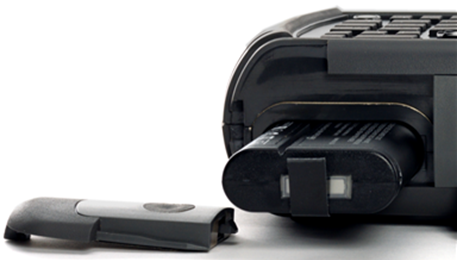
Battery Usage
When you receive your FieldFox, the lithium-ion battery is not installed, and it is partially charged to approximately 30% to preserve battery life. A lithium-ion battery has no memory effect, so it can be used partially charged, as shipped.
A fully charged battery will power your FieldFox for about four hours, so if you plan to use it for this long, you should fully charge the battery.
| The FieldFox will shut down to prevent the battery from discharging to a level that is damaging. If this occurs, charge the battery either internally or externally. Learn more about the lithium-ion battery in Chapter 34, “Working with the Lithium-Ion Battery.” |

Battery charge status is viewable:
—In the upper-right corner of the screen.
—On the Battery screen. To access the screen, select System > Service Diagnostics > Battery.
—On the battery. Open the FieldFox battery compartment door to view the battery LCD.
—Use Run/Hold to single-trigger a measurement when needed. Hold is shown on the display.
—Press System > Display > Brightness. Use the  arrows, the rotary knob, or numeric keypad to adjust the brightness to dim the FieldFox display as much as possible.
—Briefly press the power button > Standby, to switch to Standby mode when the FieldFox is not being used. Press power button again to restore power. All current settings are preserved.
| When powered by the battery only, the FieldFox can stay in Standby mode for a maximum of four hours and then it powers off automatically. When the relative battery charge drops by about 20%, the FieldFox will power off to preserve the remaining charge. |
Use ONLY a FieldFox charger to recharge a battery.
—The battery can be fully charged while in the FieldFox in about 4 hours with the FieldFox either ON or OFF.
—The battery can be fully charged externally using the external battery charger in about 4 hours.
—When the battery is removed, the FieldFox can still be powered by the AC/DC adapter.
| The FieldFox power button shut down/standby sequence includes a 10 second counter that allows you to either choose a softkey to immediately initiate the action (Standby / Shut down / Restart*), or to let the countdown counter expire after 10 seconds then perform the action. |
—To turn power ON, briefly press the power button. Boot-up takes about 1 minute.
—To switch to Standby mode (low battery drain), briefly press the power button. See the Note above concerning Stand By.
—To turn Power OFF (very low battery drain), press the power button briefly and press the Shutdown softkey. Data and instrument state are NOT automatically saved when the FieldFox is powered OFF. Learn how to save data and instrument state in Chapter 33, “File Management”, on page 913. See the Note above concerning Shut down.
—To restart FieldFox, press the power button and press Restart. See the Note above concerning Restart.
—Press Cancel to exit the power down sequence.
—You can also access the power down softkey menu choices (Standby, Shut down, Restart, and Cancel) by using the Mode hardkey:
—Press Mode
—Then More
—Then Shut down
—You can make a setting to automatically Power ON the FieldFox when a power source is connected. Learn how on “Power ON” on page 901.
Solid green | Power is ON and operating normally. |
Blinking green | FieldFox in Standby mode or in powering up. |
Solid amber | FieldFox is in the power-off state. |
Solid red | Cannot start normally. Contact support |
Not lit | FieldFox is in the power-off state. |
Solid green | Battery is fully charged. |
Blinking green | Battery is charging. Green LED blinking indicate charge status: |
Blinking amber/Green solid | Amber LED blinking indicate battery status: |
Solid red | Battery temperature is above 62°C or below -20°C. FiledFox will not power on. Ensure good ventilation and allow the unit to cool. |
Not lit | No battery installed. |
FieldFox High Temperature Protection
The following features prevent degradation or damage in the event of high internal temperatures in the FieldFox.
Do NOT store the FieldFox in the soft-case while powered ON or in Standby mode. |
How to monitor the internal FieldFox temperature:
—Press System > Service Diagnostics.
—Then Internal Temperatures.
—The average temperature that is displayed for the Internal Temperature is the average of the RF1, RF2, SB1, SB2 temperatures. These temperatures come from internal sensors embedded within the FieldFox.
The average temperature does not include the CPU or the battery temperatures. The FieldFox does not measure the CPU and battery temperatures.
The FieldFox’s internal temperature control preserves measurement accuracy and maintains the long-term reliability of the FieldFox. See also, “High-Temp Shutdown Warning (RTSA Mode Only)” on page 39.
| Measurement speed specifications do NOT apply in Temperature Control Mode. |
Entering Temperature Control Mode
At an average internal temperature of above approximately 64°C, the FieldFox enters Temperature Control mode by reducing display intensity. This should decrease the internal temperature which preserves measurement accuracy and maintains the long-term reliability of the FieldFox. Refer to Figure 2-1.
In addition, duty cycling is enabled when the internal average temperature of the FieldFox reaches the duty cycling threshold of above ~64°C. All applications (except RTSA): Power for internal circuitry is turned off between sweeps and delaying occurs for the next sweep. In RTSA mode, power is only turned off, if the FieldFox is in Single Sweep or Hold.
All applications (including RTSA): Display dims to 40% at ~64°C.
For all modes, except RTSA mode, you will see the following messages displayed for ~3 seconds:
"Automatic Meas Duty Cycling activated for thermal management"
Later if the temperatures are reduced:
"Temperatures reduced, ending Automatic Meas Duty Cycling"
For RTSA mode (where duty cycling is not possible), you will see the following messages displayed for ~3 seconds:
"Entering Auto Protect mode for thermal management"
Later if the temperatures are reduced:
"Temperatures reduced, exiting Automatic Protect Mode"
Entering Auto Protect (Maximum) Threshold Temperature Mode
At above approximately 75°C, the FieldFox enters (Maximum) Auto Protect temperature control mode by displaying the “Entering Auto Protect mode...”. See also Table 2-1 on page 40.
When you enter the Auto Protect (Maximum) Threshold, the following message is displayed:
"Entering Maximum Auto Protect mode for thermal management"
When temperature reaches the maximum protection threshold (~75°C), some applications take additional measures.
Figure 2-1 Entering Auto Protect mode message (above ~64°C)—(Displays for 3 sec)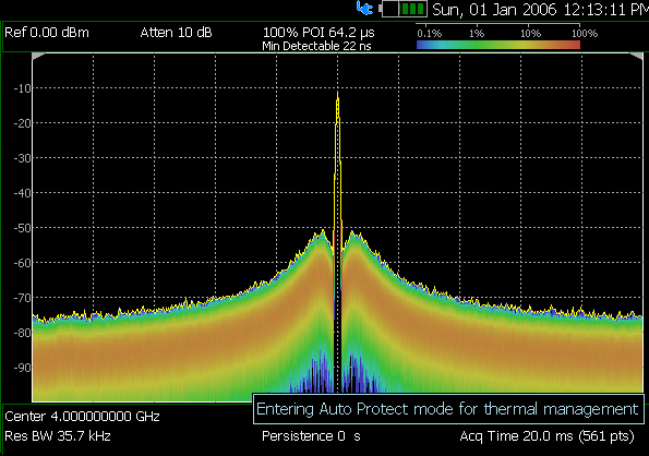
Exiting Maximum Auto Protect Threshold Temperature Mode
When the temperature drops to approximately 73.5°C, a message is displayed indicating that the FieldFox is leaving Temperature Control Mode and normal operating settings are restored (refer to Figure 2-2). See also, Table 2-1 on page 40.
When you exit the Auto Protect (Maximum) Threshold control mode, the following message is displayed:
"Temperatures reduced, exiting Maximum Auto Protect mode"
Figure 2-2 Exiting Maximum Auto Protect mode message—(~62.5°C)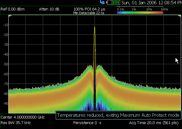
High-Temp Shutdown Warning (RTSA Mode Only)
In extreme situations, Temperature Control mode may not stop an increase in the FieldFox internal temperature. Just prior to shut down, the FieldFox will display a warning of imminent shut down and the instrument turns off. At above approximately 77°C, a Maximum Auto Protect message—(Top “WARNING...” message) displays for 9 sec. Red text at left bottom corner of display remains on until internal temperature returns to ~75.5°C. At above ~78°C, High-Temperature Shut down will engage and turn OFF the FieldFox. Refer to Figure 2-3. See also, Table 2-1 on page 40.
Figure 2-3 Shutdown Warning message—(above ~77°C) - (RTSA Mode Only!)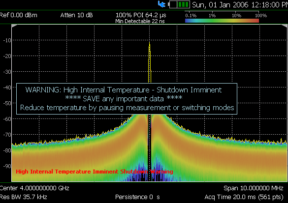
Summary of FieldFox Average Internal Temperature Protection Behavior
Threshold | Average Internal Temperature | Description of Behavior |
|---|---|---|
Duty cycling | ~64°C | Duty cycling is enabled when the internal average temperature of the FieldFox reaches the duty cycling threshold of ~64°C. Power is turned off between sweeps and delaying occurs for the next sweep. In RTSA mode power is only turned off in Single Sweep or Hold. This enables you to control your instrument’s temperature when you don’t need to make a measurement by using the “Run/Hold” hardkey to pause the sweep. All applications (including RTSA): Display dims to 40% at ~64°C. |
Maximum Protect (Initial) | ~75°C | When temperature reaches the maximum protection threshold (~75°C) some applications take additional measures. |
1 degree below shutdown (RTSA Mode Only) | ~77°C | RTSA Shutdown Warning (~77°C) — (Top “WARNING...” message displays for 9 sec). Red text at bottom of display remains on until internal temperature returns to ~75.5°C. Refer to Figure 2-3 on page 39. |
Shutdown | ~78°C | Instrument shuts down. |
Exit Duty Cycle | ~62.5°C | The temperature required to come out of the duty cycle threshold. |
Avoid Overpowering the FieldFox
The FieldFox can be damaged with too much power or voltage applied. Exceeding the maximum RF power levels shown below will cause an ADC Over Range message to appear on the screen.
| Maximum Input Voltages and Power: – RF Output Connector: 50 VDC, +23 dBm RF – Ext Trig/Ref Connector: 5.5 VDC RF Input: – +27 dBm RF, ±50 VDC Max. (N991xD, N993xD) – +25 dBm RF, ±40 VDC Max. (N995xD, N996xD) DC Input: 15 VDC, 4 ADC, 60 Watts maximum when charging battery Learn more about Maximum power and voltages in the FieldFox Data Sheet. Refer to the D-Series FieldFox Data Sheet Appendix B:, “Specifications/Data Sheet,” on page 979. |

On D-series models, the Power Management feature can automatically disable the 10G Ethernet interface (LAN1) when the instrument enters the Secondary Maximum Protection State due to battery or temperature conditions. If this occurs during an active IQ Streaming session, streaming to the 10G interface stops automatically. New 10G IQ Streaming sessions cannot be started until the protection state is cleared.
—Press System 7 > Service Diagnostics.
—Then Power Monitor.
—The Power Monitor UI displays the power consumption of the SFP system. When the SFP system is disabled, the power consumption should drop to 0 W. Refer to Figure 2-4
By default, the lan1 (10 G Ethernet) interface is disabled after a reboot. lan1 can be enabled from Network Configuration ( System 7 > System Configuration > More > LAN ) by selecting the lan1 adapter and setting Adapter Status to Up. The interface is also enabled automatically when 10 G Ethernet is selected as the IQ Streaming connection type ( Meas Setup 4> IQ Analysis > Settings > Connection Type > 10G Eth (SFP+) ) When the FieldFox is in the Secondary Maximum Protection State, a warning message appears when attempting to enable 10 G Ethernet. lan1 remains disabled until the protection state ends. The system also logs this warning message in the event log. See Figure 2-5 and learn how on “Event Log” on page 904
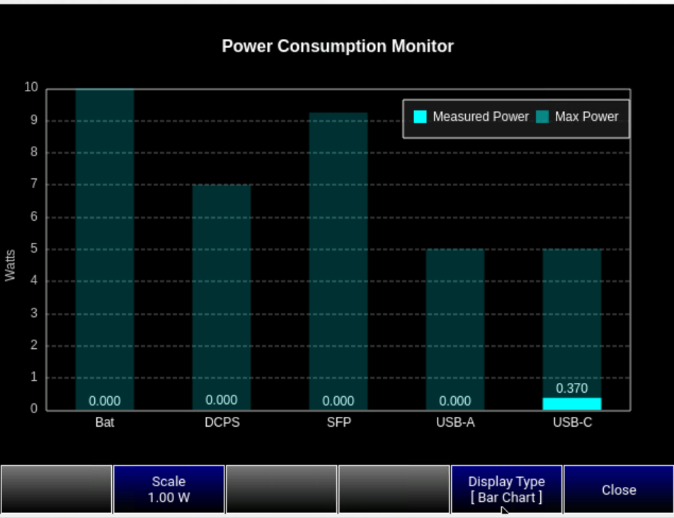
Figure 2-5 10G LAN Streaming with SFP Power Inhibited Warning Message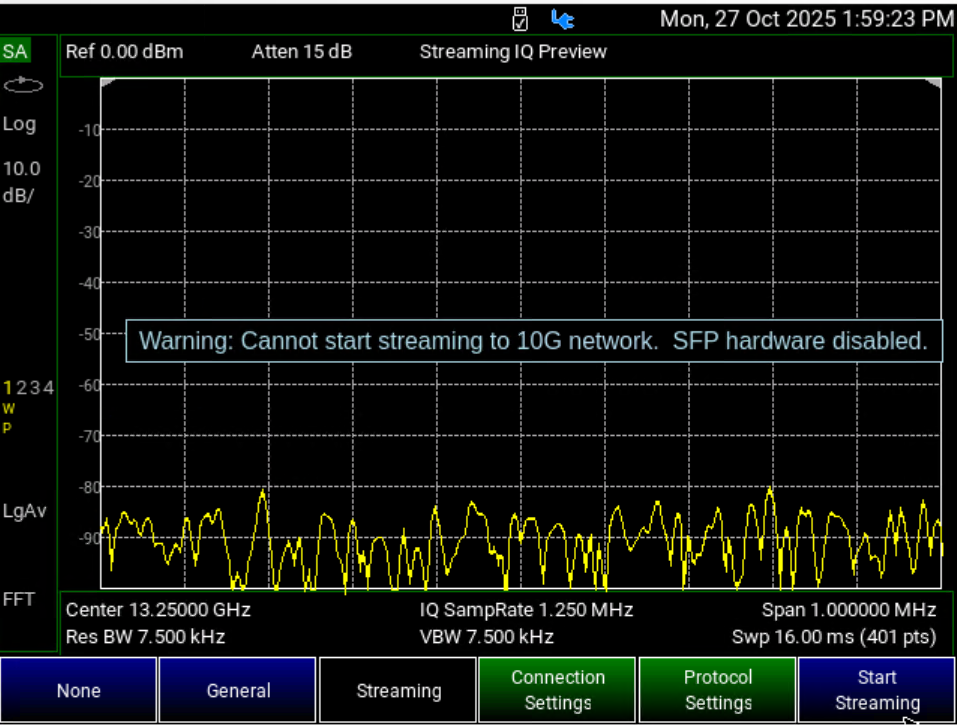
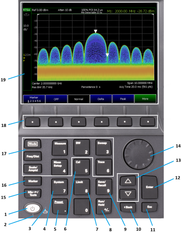
1 | Power | ON: press momentarily. STAND BY: with FieldFox power ON, press briefly. OFF: press and hold until the FieldFox shuts off (about 4 seconds). | |
2 | Power Status LED | Green (solid) - FieldFox is powered on and operating normally. Green (blinking) - FieldFox in Standby mode or in powering up. Amber (solid) - FieldFox is OFF and AC adapter connected. Red (solid) - FieldFox cannot start normally. Contact support. Not lit - FieldFox is OFF and no AC adapter connected.
| |
3 | Battery Status LED | Amber/Green when No AC adapter connected. Green when AC adapter is connected indicate battery is charging. Red (solid) - Battery temperature is above 62°C or below -20°C. No AC adapter connected and FiledFox will not power on. Ensure good ventilation and allow the unit to cool. Not lit - No battery installed. | |
4 | System | Displays a sub-menu for system setup | |
5 | Preset | Returns the analyzer to a known state | |
6 | Cal | Displays a sub-menu for calibration functions | “Calibration Method Summary” on page 153” on page 153 |
7 | Limit | Sets limit lines for quick Pass/Fail judgment | |
8 | Run/Hold | Toggles between free Run and Hold/Single operation. | |
9 | Save/Recall | Saves the current trace or recalls saved data from memory | |
10 |
| Returns to the previous menu selection. | -- |
11 | Esc | Exits and closes the Active Entry dialog box or clears the character input | -- |
12 | Enter | Confirms a parameter selection or configuration | -- |
13 | Arrow keys | Increases or decreases a value or setting. | -- |
14 | Rotary knob | Highlights an item for selection, or enables incremental changes to values. | -- |
15 | Mkr-->Tools | Displays a sub-menu for marker functions | |
16 | Marker | Activates marker function | |
17 | Function keys | Includes: Freq/Dist, Scale/Amptd, BW, Sweep, Trace, Meas Setup, Measure, and Mode. | Refer to specific Mode. |
18 | Softkeys | Allows selection of settings for configuring and performing measurements, and for other FieldFox functions. | -- |
19 | Screen | Transflective screen, viewable under all lighting conditions. If you are using your FieldFox in direct sunlight, you do not need to shield the display from the sunlight. In bright lighting conditions, the display is brighter and easier to read when you allow light to fall directly on the screen. Alternative color modes exist that maximize viewing in direct sunlight conditions, as well as other conditions such as nighttime work.
|
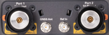
Port 1 | For CAT and NA measurements, use to make reflection measurements. Maximum: ±50 VDC, +27 dBm RF (N991xD/3xD) Also, for SA source output in SA mode. | “CAT Mode Settings” on page 57 |
Port 2 | For SA, use to make all measurements. For CAT, NA, and VVM mode, use to make Port 2 transmission measurements. Maximum: ±50 VDC, +27 dBm RF (N991xD/3xD) | |
GNSS Ant | SMA (f) connector for use with built-in GPS. Produces a settable 3.3 VDC or 5 VDC bias voltage for the antenna pre-amplifier. Use with a GPS antenna such as N9910X-825. Other GPS antennas can also be used. | |
Ref In | SMA (f) connector for use with Frequency Reference Source. Maximum: 5.5 VDC. | “Frequency Reference Source” on page 890.
|

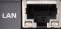
| RJ-45 (CAT 7 cables are required for EMC compliance) Download the latest version of the software at: www.keysight.com/find/fieldfoxsupport | |
| IF Out used in SA mode for external signal processing. | |
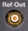
| Frequency Reference Source Output. | |
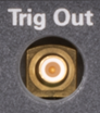
| Trigger Output (ERTA mode). | Chapter 26, “ERTA (Extended Range Transmission Analysis) Mode - Option 209”, on page 695 |
| External Trigger Input signal. | |
| Factory Use only. | |
| bHigh-speed USB-C 3.0/DP Out port can be connected to your PC’s standard USB port for SCPI programming, data transfer and file saving. For EMC compliance, cable length must be <3 meters and the unit must operate in battery mode (No AC adapter connection). IMPORTANT! It is recommended that only USB certified cables are used with the FieldFox. | Chapter 32, “Using the USB-A/C Port to send SCPI Commands and Queries”, on page 911 |
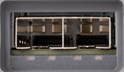
| bHigh-speed USB-A 3.0 connectorsa used to connect a power sensor for Power Meter Mode. Also used for SCPI programming, data transfer and saving file to a USB flash drive. IMPORTANT! It is recommended that only USB certified cables are used with the FieldFox. | Chapter 32, “Using the USB-A/C Port to send SCPI Commands and Queries”, on page 911 |

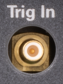

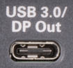
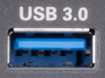
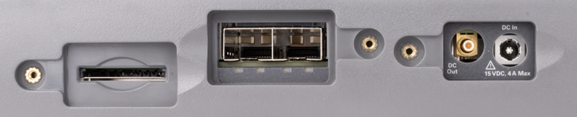
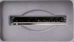
| Secure Digital slot. Use to extend the memory of the FieldFox and data saving to the SD card. | |
| SFP+, 2 ports, hot-swappable sockets compatible with 10 G Ethernet standard for high-speed data transfer, including IQ Streaming applications. For RJ-45 transceiver modules, CAT 7 cables are required for EMC compliance. | |
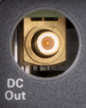
| DC Out for use with external DC Bias. | |
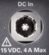
| DC In power connector used to connect to the AC/DC adapter. Maximum: 15 VDC, 4 ADC. |
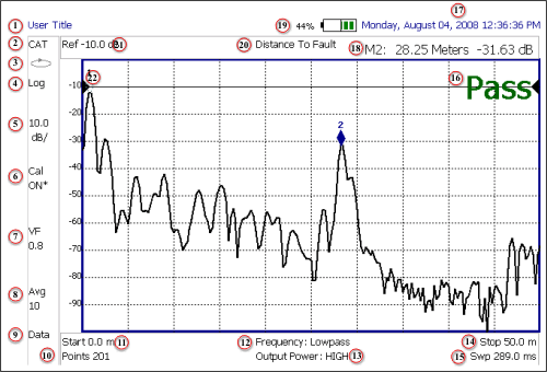
1 | Title – write your own text here | |
2 | Current Mode | -- |
3 | Run / Hold | |
4 | Display Format | Mode dependent |
5 | Scale/division | Mode dependent |
6 | Calibration Status (CAT and NA) Detection Method (SA) | |
7 | Velocity Factor (Fault Meas) | |
8 | Averaging Status and Count | Mode dependent |
9 | Data / Mem Display (CAT and NA) | “All about Trace Math” on page 850 |
10 | Resolution Setting | Mode dependent |
11 | Measurement Start Freq or Distance | Mode dependent |
12 | Bandpass / Lowpass setting (Fault Meas) | |
13 | Output Power Level (CAT and NA) | |
14 | Measurement Stop Freq or Distance | Mode dependent |
15 | Actual Sweep Time | Mode dependent |
16 | Limit Line Status | |
17 | Time and Date | |
18 | Marker Readout | |
19 | Battery Status | |
20 | Measurement Type (CAT and NA) | -- |
21 | Acquisition | Mode dependent |
22 | Reference Position | Mode dependent |
Many settings on the FieldFox require the entry of numeric values.
Use any combination of the following keys:
—Numeric 0–9 keys, along with the polarity (+/-) key.
—Up/Down arrow keys () to increment or decrement values.
—Rotary knob to scroll through a set of values.
—Back erases previously entered values.
—Esc exits data entry without accepting the new value.
To complete the setting, press Enter or a different softkey or hardkey.
Many times after entering numeric values, a set of multiplier or suffix softkeys are presented. The following explains the meaning of these abbreviations.
Select Frequency multipliers as follows:
—GHz Gigahertz (1e9 Hertz)
—MHz Megahertz (1e6 Hertz)
—KHz Kilohertz (1e3 Hertz)
—Hz Hertz
Select Time multipliers as follows:
—ms milliseconds (1e–3)
—us microseconds (1e–6)
—ns nanoseconds (1e–9)
—ps picoseconds (1e-12)
—Never store connectors, airlines, or calibration standards loose in a box. This is a common cause of connector damage.
—Install protective end caps when connectors are not in use.
—Keep connector temperature the same as the test instrument. Holding the connector in your hand or cleaning connector with compressed air can significantly change the temperature. Wait for connector temperature to stabilize before using in calibration or measurements.
—Do not touch the mating plane surfaces. Natural skin oils and microscopic particles of dirt are difficult to remove from these surfaces.
—Do not set connectors contact-end down on a hard surface. The plating and mating plane surfaces can be damaged if the interface comes in contact with any hard surface.
—Wear a grounded wrist strap and work on a grounded, conductive table mat. This helps protect the analyzer and devices from electrostatic discharge (ESD).
—Refer to Appendix A:, “Connector Care Review,” on page 977.
| Because of the very small and precise mechanical tolerances of mmWave connectors, minor defects, damage, and dirt can significantly degrade repeatability and accuracy. In addition, a dirty or damaged connector can destroy connectors that are mated to it. For this reason, NEVER use a damaged connector. See also “Connector Care” with the PNA Help https://rfmw.em.keysight.com/wireless/helpfiles/N52xxB/Tutorials/Connector_Care.htm. See also, https://www.keysight.com/us/en/assets/9018-04357/user-manuals/9018-04357.pdf (85051-90032). |