Now that the calibrations are completed, we'll apply the corrections to the default miltitone signal, then switch to a custom IQ signal.
Apply the Corrections to the Default Multitone Signal
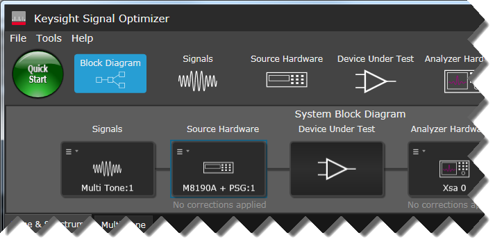
Select Source Hardware in the Block Diagram. Notice the "No corrections applied" indicator under the Source Hardware block.

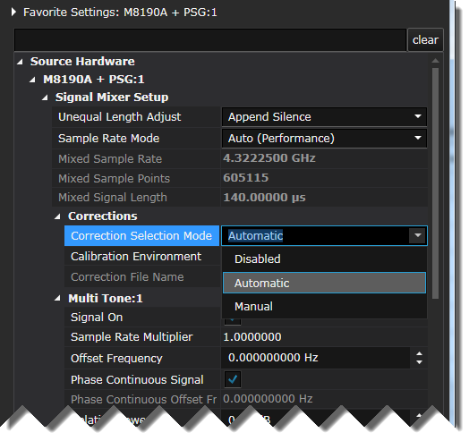
In the Favorite Settings property grid, set Correction Selection Mode to Automatic.
Click Download All Signals to apply the corrections, then click Run when the download is finished.


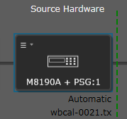
Notice the indicator under the Source Hardware block changed from "No corrections applied" to "Automatic" with the corrections filename below it and a graphic representation of the calibration plane in green.
Observe the improved signal quality after applying pre-corrections to the source hardware.
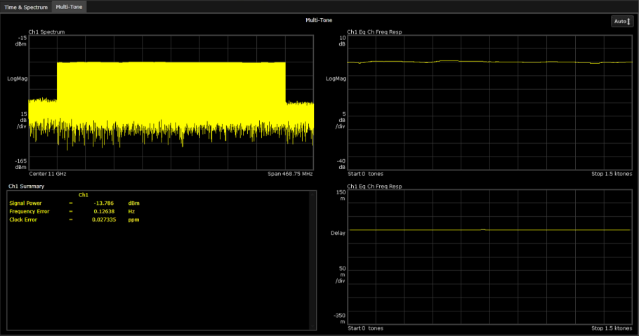
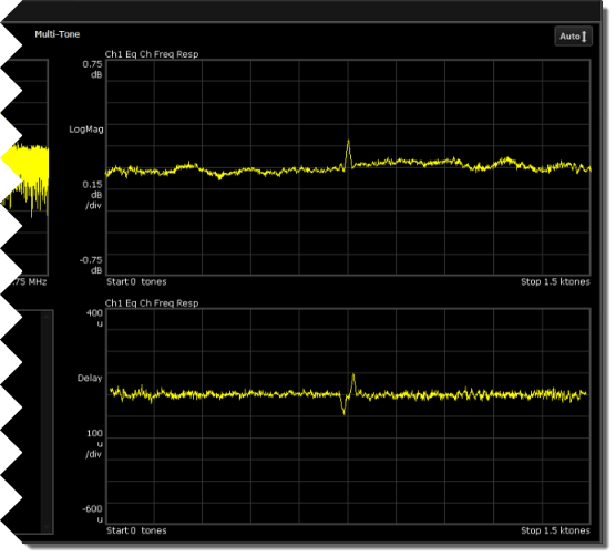
Click Auto for a magnified view of the frequency response. While significantly better, the signal is still not optimized. A flattened signal has been applied to the Device Under Test, but variations in the analyzer path still need to be corrected.
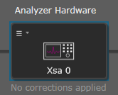
While the signal is still running, select Analyzer Hardware in the Block Diagram.
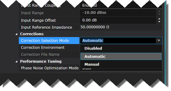
In the Favorite Settings property grid, turn on the receiver plane corrections by setting Correction Selection Mode to Automatic.
If you performed a Source Only calibration, leave this setting in the default Disabled state because you will not have analyzer corrections to apply.
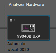
The indicator under the Analyzer Hardware block changed from "No corrections applied" to "Automatic" with the corrections filename below it and a graphic representation of the calibration plane in green.
If you performed a Source Only calibration, you will see "No corrections applied" under the Analyzer Hardware block and you will not see any additional improvement in signal quality.
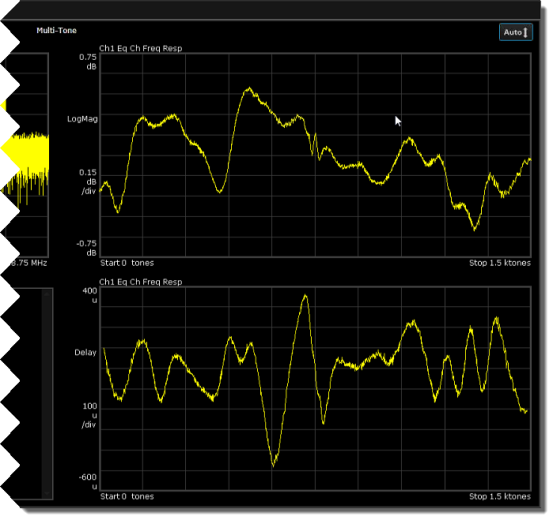
Notice that the signal quality is improved after analyzer corrections have been applied.
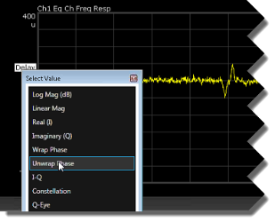
In the Ch1 Eq Ch Freq Resp trace, right-click Delay and select Unwrap Phase.
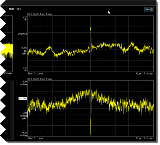
Click Auto for a magnified view of the frequency response. The signal is now corrected to well under +/- 1 degree of phase and +/- 0.2 dB of amplitude.
Since the calibration is independent of the signal type (other than center frequency and amplitude), we can delete the multitone signal and replace it with something more interesting like a Custom IQ signal. Before we do that, let's make sure that the Signal Optimizer automatically created and removes measurements as needed.
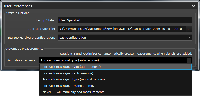
Open Tools > Preferences. Under Automatic Measurements, set Add Measurements to For each new signal type (auto remove).
Click the Signals icon to view the Signals resource panel.
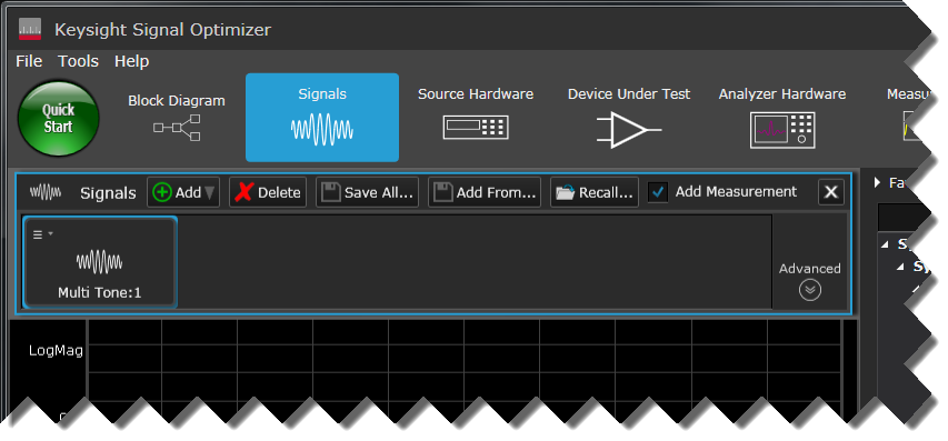
In the Signals panel, Click the Multi Tone:1 signal and click Delete.
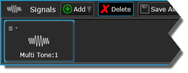
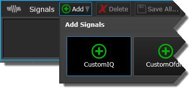
Click Add > CustomIQ.
Click the Custom IQ:1 signal to display the signal's property grid.
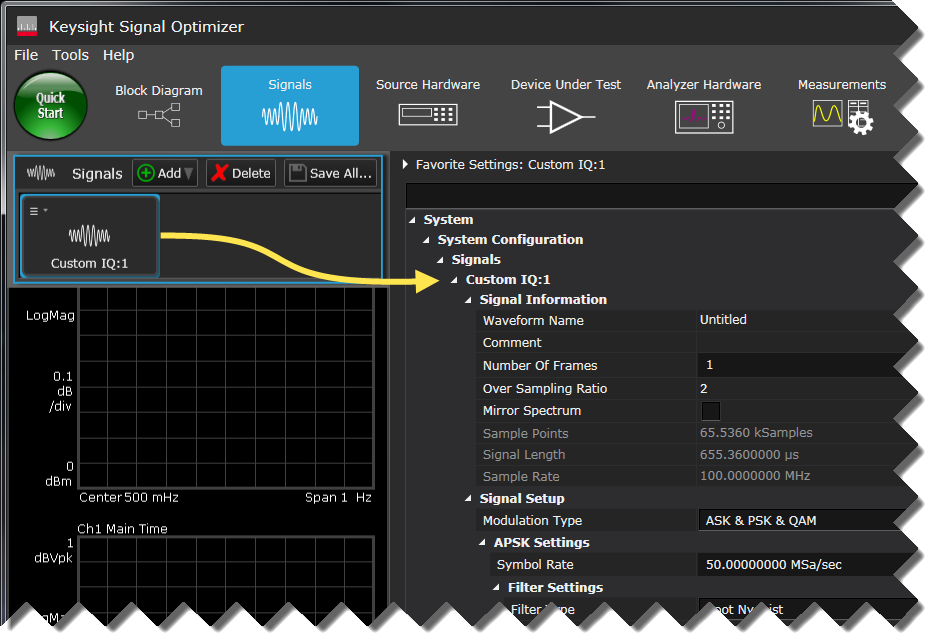
Set the Symbol Rate to 400 MS/sec to occupy most of the analyzer's bandwidth.
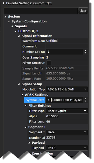
Click Download All Signals and click Run when the download is finished.


Click the CustomIQ measurement display panel tab to observe the corrected Custom IQ signal. Notice the EVM is less than 0.5 percent after corrections.
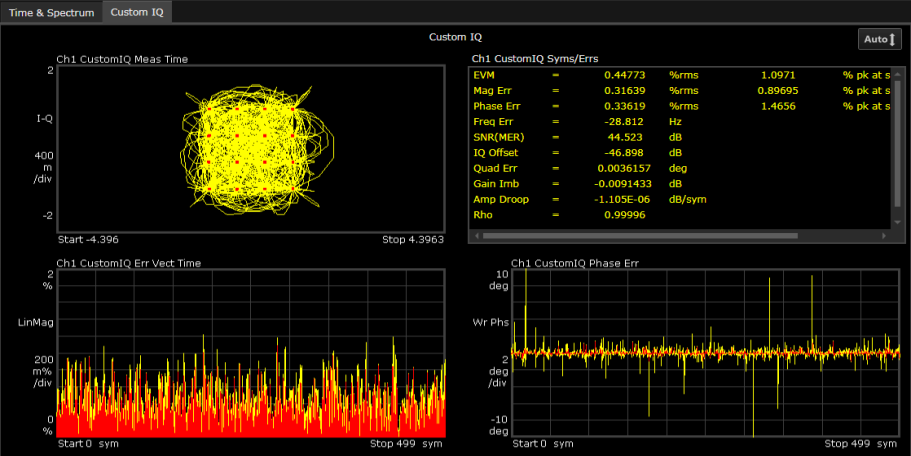
Stop the measurement and go to the next step.
