This topic describes the procedure for performing an AoA directional-finding measurement.
AoA (Angle of Arrival) is used for direction finding by measuring the angle of signal arrival at multiple receivers to locate emitters.
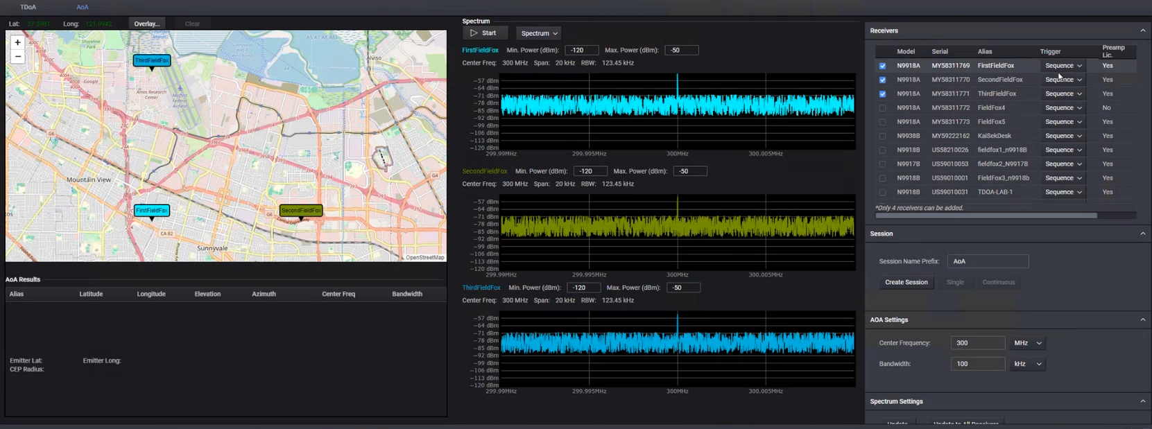
Add receivers required for your measurement.
Click the Directional-Finding tab and then select AoA.
From the Receivers section on the right, select the checkboxes for receivers that you want to use in your AoA measurement.
The selected receivers appear on the map on the left. The Map displays the current latitude and longitude of the center of the screen displayed in the map.
From the Session section on the right, click Create Session to initiate a session for the AoA measurement.
From the AoA Settings section on the right, adjust the AoA settings, including the center frequency and bandwidth.
From the Spectrum Settings section on the right, adjust spectrum and receiver settings as per your specific requirements.
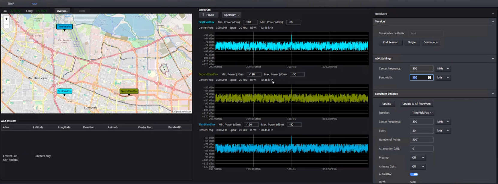
From the Map Settings section on the right, configure map settings to toggle on or off the display of following elements based on what you want to display on the map.
Heat map
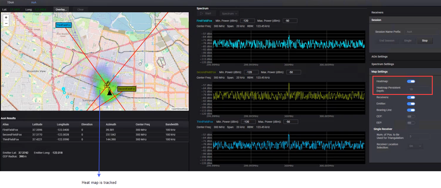
If Heat Map is set to On, you can also track heat map of the emitter by specifying Heat Map Persistent Depth value.
CEP (Circular Error Probable), EEP (Elliptical Error Probable), and Bearing Lines on the map
See Example below to know more about these elements on the AoA map.
From the Session section on the right, click Single to run a single AoA measurement to locate target emitter. Click Continuous if you want to run the AoA measurement continuously to track the emitter over time until the Stop button is clicked.
When the AoA measurement is generated, the "Emitter" along with other selected element(s) such as heat map are displayed as shown in the example screen below.
Example of successful target (emitter) tracking with Continuous AoA measurements until Stop is clicked.
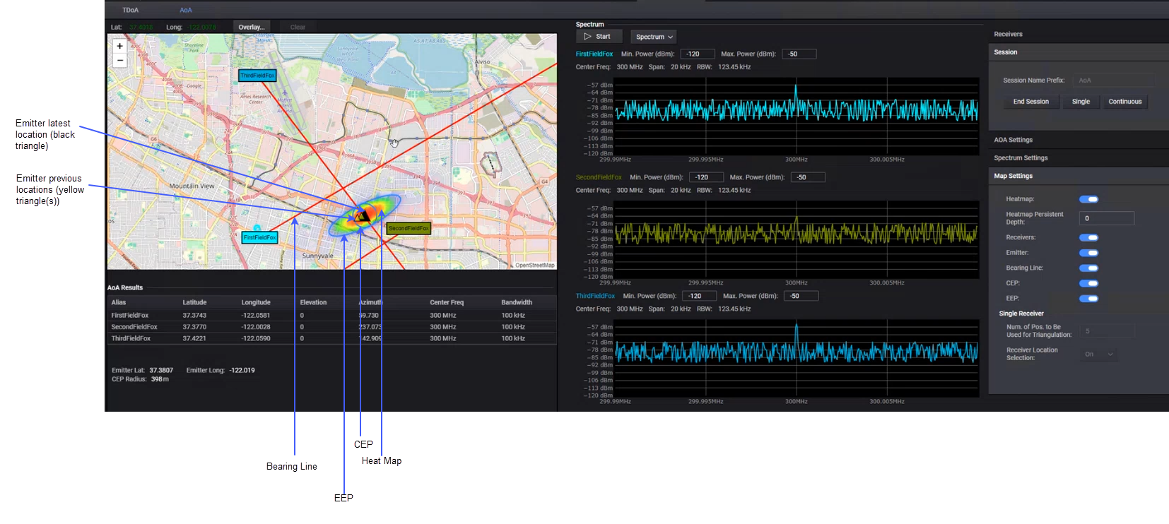
View the results on the map and in the table displayed in the AoA Results section below the map.
Click End Session to conclude the session after analyzing emitter data.
The Heat Map Persistent Depth setting in AoA > Map Settings section is used to set the depth for which you want to track the heat map path of the emitter over time. It helps you to view the movement and history of the emitter's heat map on the AoA map. This is useful for understanding the emitter's trajectory and behavior.
When set, the Persistent Depth setting leaves a track of the heat map on the AoA map, showing the previous locations of the emitter.
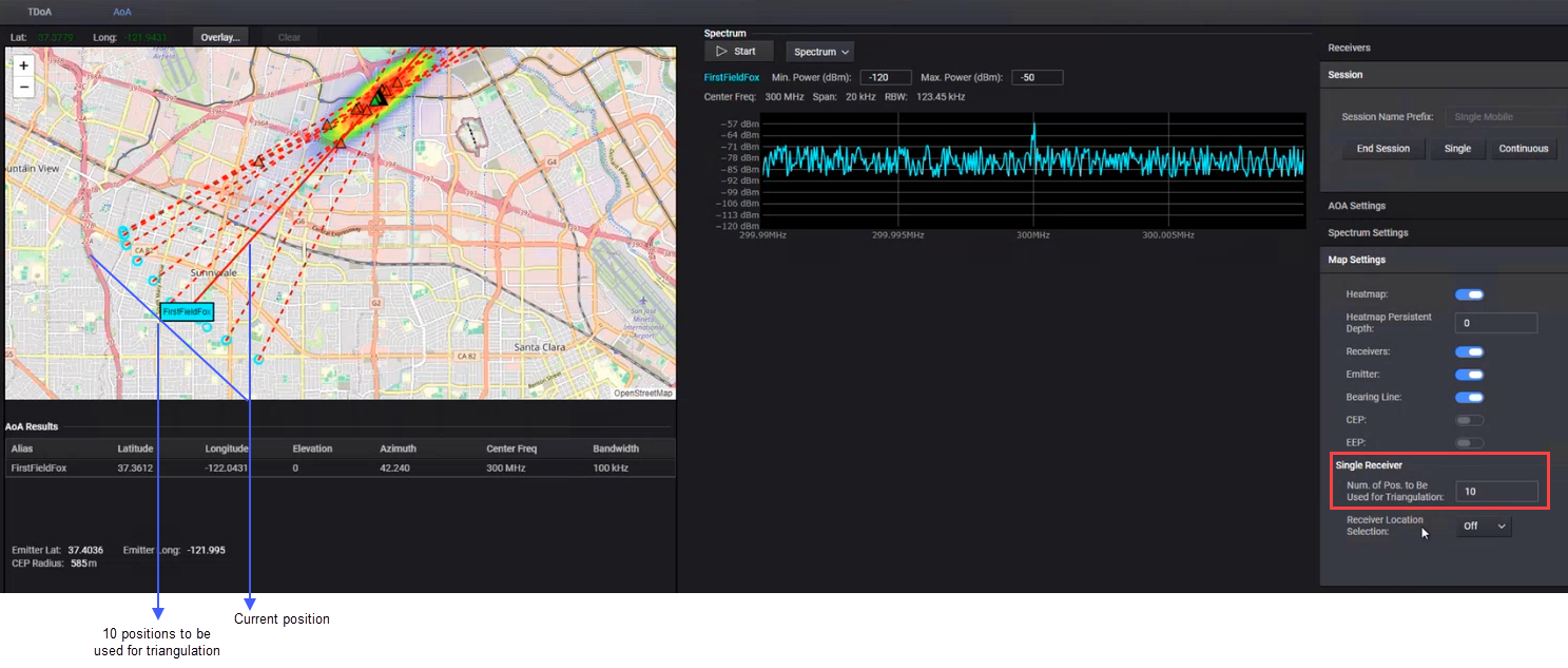
The Single Receiver settings in AoA > Map Settings section allow AoA to be performed with a single receiver, making it suitable for single equipment mobile situation. This is useful for scenarios where multiple receivers are not available or practical.
With only one receiver, the Single Mobile AoA feature uses single receiver's past measurements to estimate the emitter's location by triangulating the data points where the receiver was previously located.
You can configure the following two settings for the Single Receiver AoA measurement.
Num of Pos. to be used for Triangulation - You can adjust this value to increase/decrease the number of positions (past and current data points of emitter) that should be used to estimate the emitter's location. By default, this value is set to 5. For example, in the sample screen below, the number of positions used for triangulation is 10, which is represented by ten lines in the heat map.
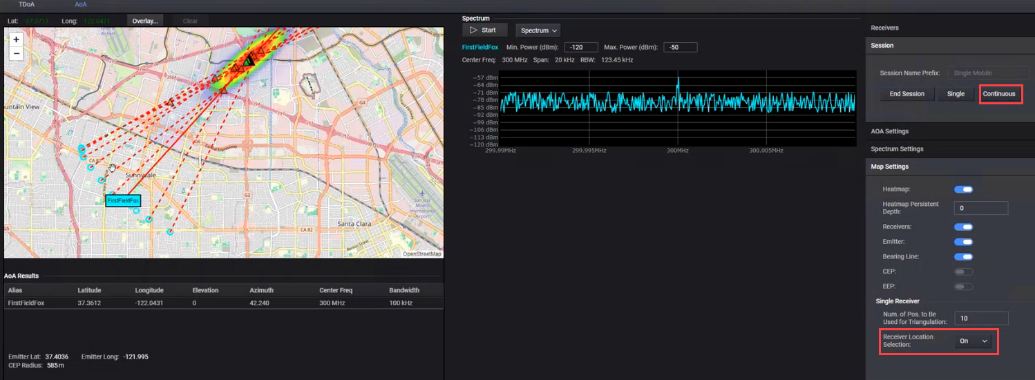
Receiver Location Selection - When doing Continuous AoA measurement, it is recommended that you enable this option so that the measurements taken when the receiver is stationary are not used for triangulation and therefore not shown on the map.
When this option is set to On, it selects measurements based on the receiver's movement thereby not using measurements taken when the receiver is stationary (e.g., stuck in traffic).
When this option is set to Off, each measurement is used and shown on the map to estimate the emitter's location.
In the example screen below, the AoA measurement is Continuous and the Receiver Location Selection is set to On ensuring that only those measurements are used and shown when there was a receiver movement.
Expanding and collapsing windows (tabs)
You can expand and collapse (close) windows by clicking on the corner arrows.