Without Option 001, the calibration is performed in the Network Analyzer and recalled into the N1500A software as a CalSet. This is needed for Coax or Waveguide sample holders where the sample is cut to fit inside a waveguide or coaxial transmission line.
Freespace Calibration is NOT supported in the FieldFox analyzers.
First, a 2-port calibration is performed at the antenna inputs. This calibration cal be performed at the time, or recalled from a Cal Set that is stored in the analyzer.
The GRL cal is performed as a second calibration, 'on top of' the 2-port calibration.
This second calibration, performed with the transmit and reflect antennas, is challenging for many reasons.
The GRL Cal is similar to a LRM cal (Line, Reflect, Match) which is in the TRL family of cals. In these calibrations, three standards are used to 'show' the VNA what the following perfect conditions look like.
Line - The sample holder is left empty. All energy is transmitted through the air into the opposite receive antenna. This is similar to a THRU standard.
Reflect - A metal plate is used to reflect all of the incident energy back to the transmitter. With a metal plate, both ports are cal'd with a single standard. The metal plate is also used as an Isolation standard, as no signal should be detected at the opposite antenna.
Match - This would be a perfect Load, where all of the transmitted energy is absorbed and NO reflections are measured at the transmitter. This would best be performed by pointing the transmit antenna straight up into the open sky. Unfortunately, this is not practical most of the time. So reflections are Gated out of the reflect (metal plate) measurement.
Select Measure, then Freespace Calibration, the select from the following:
This selection creates a freespace cal set from an existing coaxial/waveguide cal set by measuring a metal plate and an empty fixture.
It also makes the measurements required for a gated response isolation cal, which can be performed independently by selecting the item below.
See GRL Measurement Considerations for additional information.
This selection is the same as above, except that the tier 1 cal is not performed. All of the measurement setup is gated from the measurement results, leaving only the response of the MUT. Because gating is responsible for much of the cal, many data points are required to make an Alias-free TD transform which can be slow.
A last prompt asks 'do you want to add the gated isolation cal'. If yes, it does a little more gating. If no, you can save it and apply it later?
This selection creates a full two-port calibration based on measuring response and isolation standards.
The various match imperfections are assumed to be perfect.
This calibration is useful when using the Tran e Fast or Stack/Tran u&e models and a free-space fixture.
This selection guides you through a gated response isolation calibration.
This selection toggles (On | Off) the application of a gated resp/isol cal to the next measurement.
The following table shows an ordered list of the dialogs that are presented for each GRL Cal Type.
2 tier GRL |
1-tier GRL |
2-port trans resp/isol |
Gated resp/isol |
Corrugated Waveguide Response |
|
Select
Cal Set |
|
||
|
|
|||
Measure Plate w/skip |
||||
|
|
|||
|
|
|
Choose which standard (empty fixture or metal plate) to measure first.
This dialog appears ONLY for the 2-tier GRL Cal. (This is the first tier.) You have two choices.
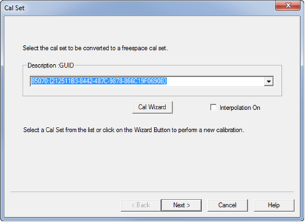
(Skip to step 2 if you already have a 2-port cal.) Click Cal Wizard to perform a new calibration on the connected instrument. The new Cal Set appears as a choice in the above dialog.
Select an existing Cal Set stored in the analyzer, then click Next >. This message may appear if the settings in the instrument do not match the settings in the select Cal Set. Select a different Cal Set.
Interpolation On - When checked, the original calibration can be reused.
The following Set Time Domain Parameters dialog appears.
This dialog appears after the 2-port calibration is performed or recalled or if the 1-tier GRL Cal was selected.
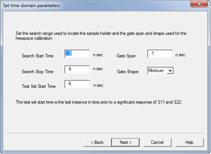
Select the Time Domain parameters for the Gating portion of the GRL Freespace calibration.
Search Start and Stop Times The metal time domain response occurs between these times.
Gate Span Select the amount of time to be gated into the measurement.
Gate Shape Defines the filter characteristics of the gate function. Choose from Minimum, Normal, Wide, Maximum. Learn about Gating in the PNA. Requires an internet connection. Set the time domain parameters to be used for gating during the GRL calibration.
Test Set Start Time (appears ONLY on Tier 1 GRL) You select where the Gating Start time occurs. The goal is to Gate out the time from when the signal first encounters reflections in the PNA until the Search Start time.
Then click Next >
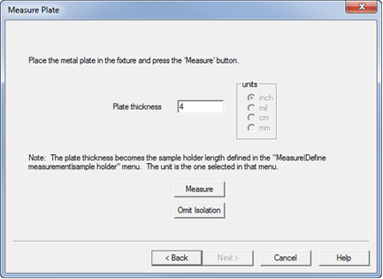
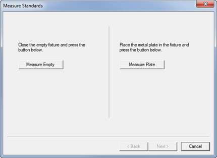
Enter the thickness of the metal plate.
Place the metal plate in the fixture
For ONLY Perform two port transmission resp/isol cal, choose EITHER Measure (Isolation) or Omit (skip) Isolation.
For all others, press Measure.
Then click Next >
![]()
Remove the metal plate and press Measure.
Then click Next >
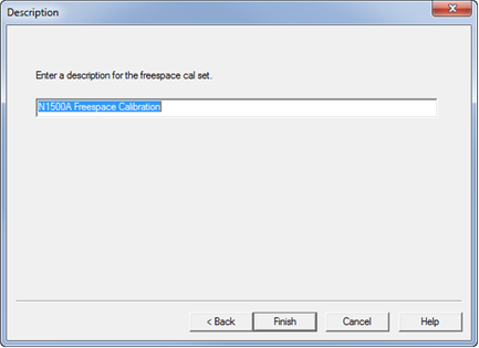
Enter a name for the completed GRL calibration. This Cal Set can be recalled at any time.
Then click Finish to compute the new calibration.
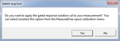
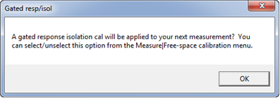
Choose whether to use the Gated Response Isolation cal that was also computed when the GRL cal set was calculated. This calibration is independent of the GRL cal.
Yes - Apply it to the existing cal now.
No - Do NOT apply it.
To later Apply this Cal, click Measure, then Freespace Calibration, then Apply gated resp/isol cal.
This message appears ONLY after the Gated Response Isolation Cal.